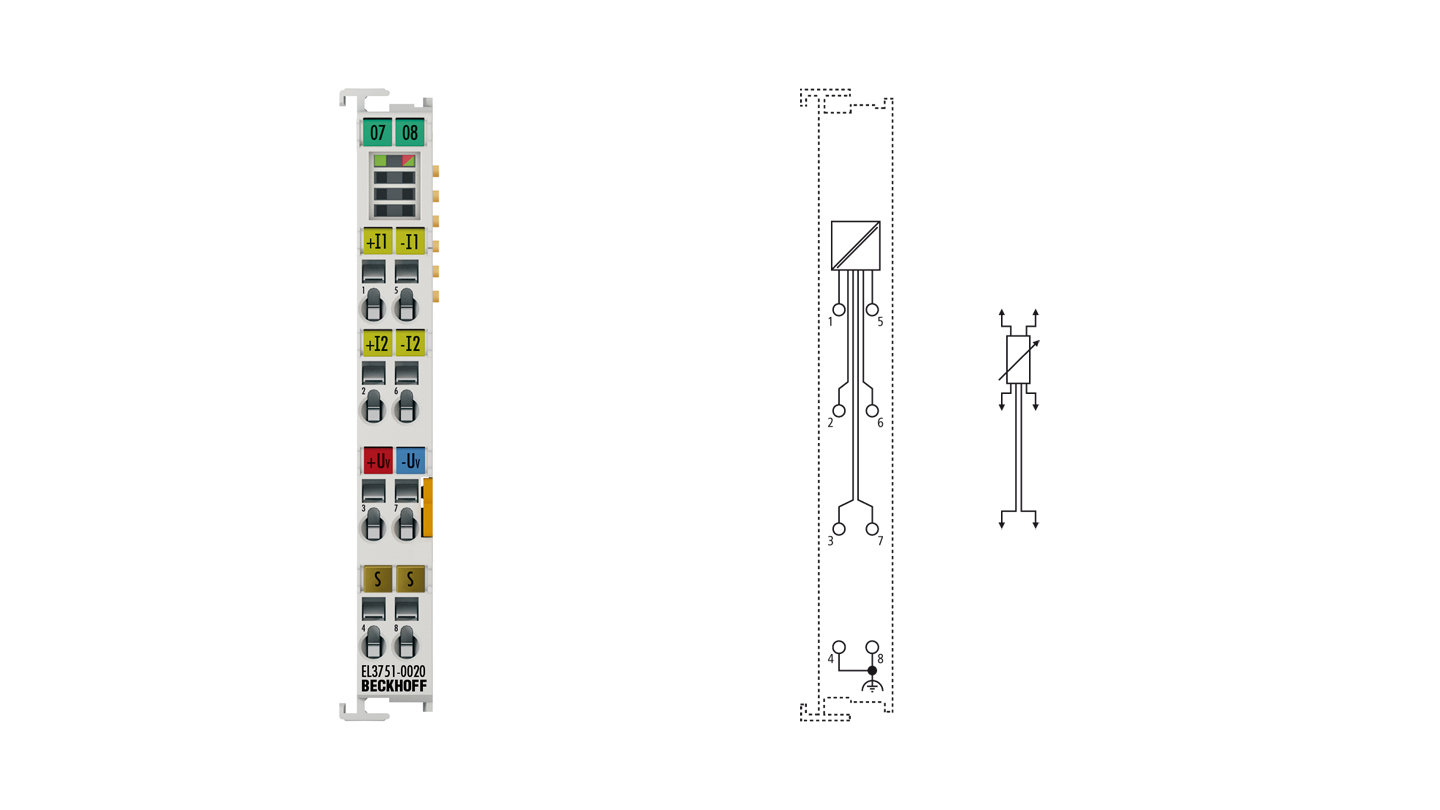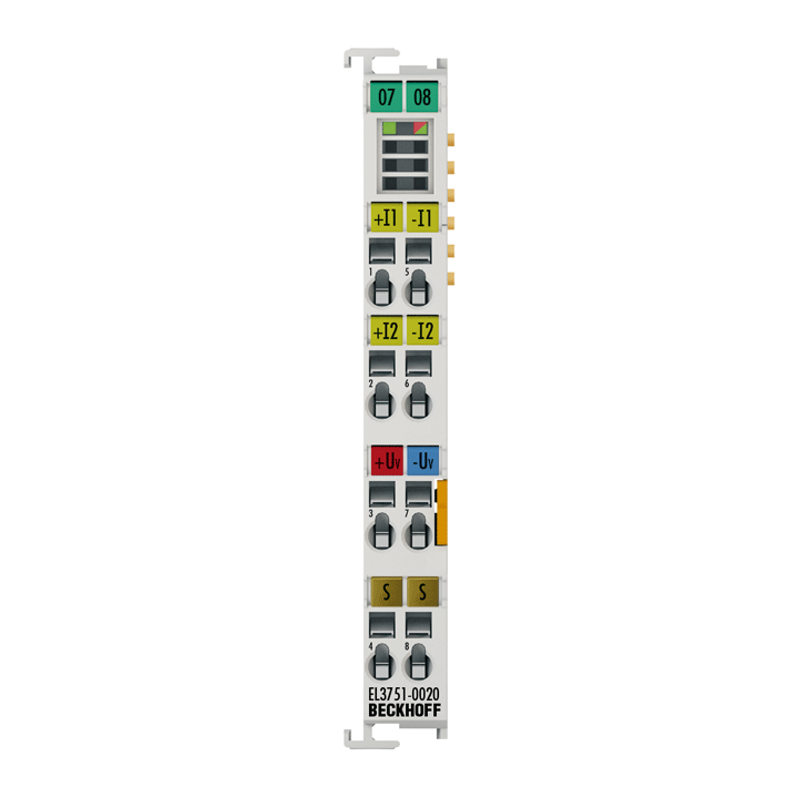
The EL3751-0020 analog input terminal is part of the new generation of analog EtherCAT measurement terminals. The nominal measuring range of the input channel can be comprehensively parameterized, both electrically and on the software side:
- voltage measurement: ±5 mV to ±30 V (incl. ±10 V), 0…10 V, 0…5 V
- current measurement: ±20 mA, 4…20 mA, 0…20 mA, NAMUR NE43
- resistance measurement: 0…5 kΩ
- electrical resistance R in 2-/3-/4-wire connection
- RTD measurement in 2-/3-/4-wire connection
- strain gauge/load cell: ¼ bridge (350 Ω + 120 Ω), ½ bridge (±16 mV/V) and full bridge (±32 mV/V) with integrated supply in 2-/3-/4-/5-/6-wire connection
- potentiometer: min. 1 kΩ
The measuring ranges generally reach accuracy class 0.01%. For further information please refer to the documentation. Through the feature “ExtendedRange” the user has the full technical measuring range available, up to 107% of the specified nominal measuring range, depending on the measuring range. This feature can be disabled, in order to ensure compatibility with the “LegacyRange” of the EL30xx/EL31xx series.
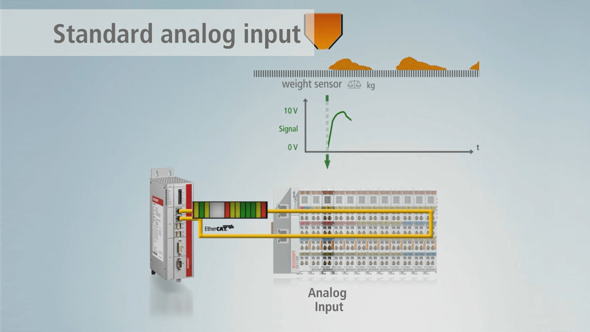
To suppress aliasing effects, the input channel features two configurable numeric software filters up to 39th order FIR/6th order IIR. The filters can be preselected or freely described, so that a band stop or a band pass can be realized. The measurement at the differential input channel is digitized with a resolution of 24 bit and 10 ksps and is transmitted to the higher-level automation device electrically isolated and optionally with oversampling. The data rate can be internally reduced, in which case the filters have to be adjusted accordingly. Non-linear characteristic sensor curves can be corrected flexibly through an integrated sampling points table. Simple mathematical operations are also possible.
The integrated supply and the switchable auxiliary resistors enable direct connection of a resistor bridge (strain gauge) or a load cell, a fixed ohmic resistor, a PTC or a potentiometer. The signal state of the EtherCAT Terminal is indicated by light emitting diodes. Each terminal has a unique ID number.
The individual Beckhoff factory calibration certificate can be downloaded here for each device. Recalibration (ZS9001) is possible via Beckhoff Service.
Product status:
regular delivery
Product information
| Technical data | EL3751-0020 |
|---|---|
| Number of inputs | 1 |
| Power supply | via the E-bus |
| Oversampling factor | n = 1…64 |
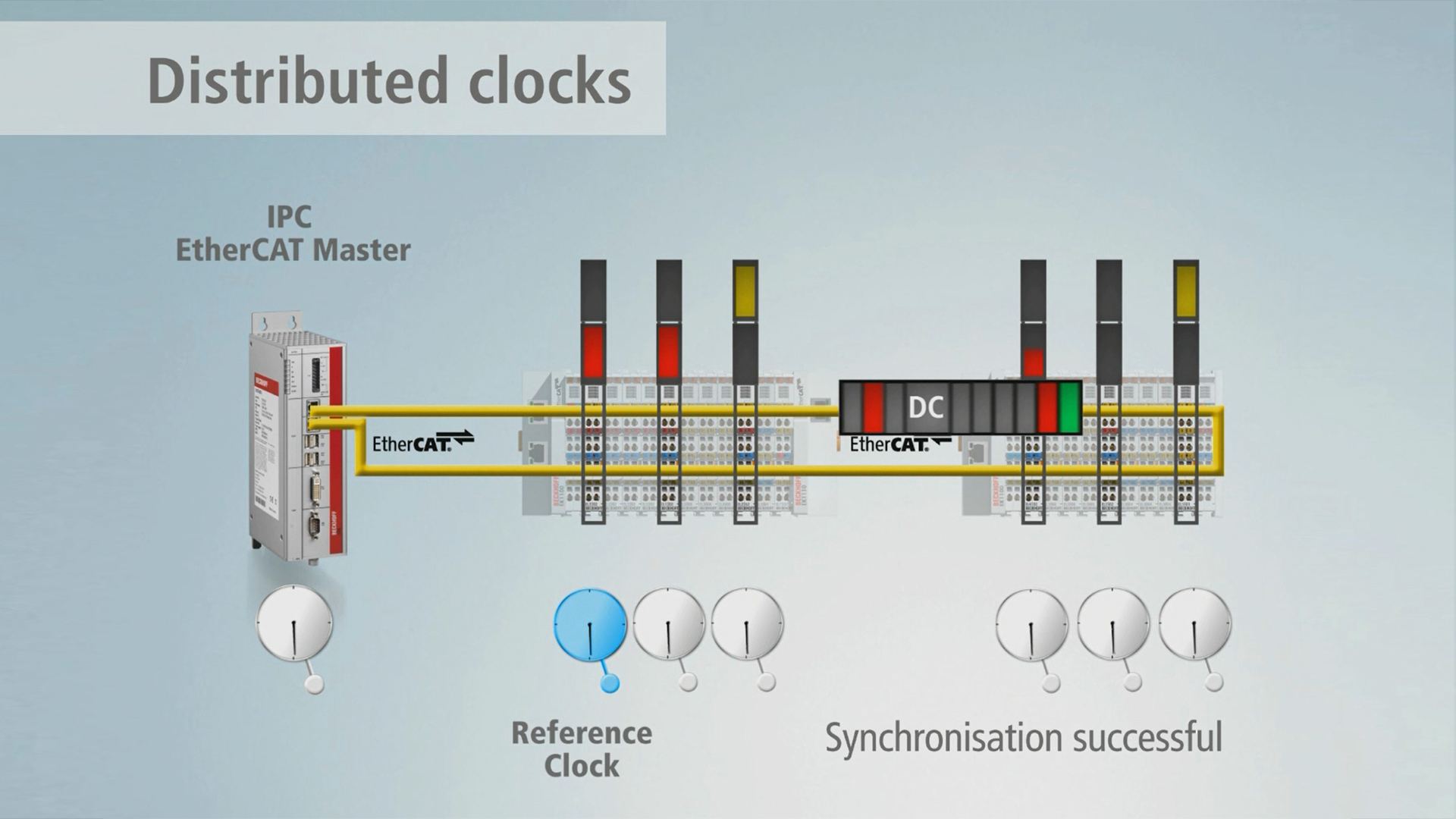
| Distributed clocks | yes |
| Distributed clock precision | << 1 µs |
| Internal resistance | > 500 kΩ (30 V); > 4 MΩ (others); 150 Ω (current) |
| Input filter limit frequency | 3 kHz |
| Dielectric strength | max. 36 V |
| Conversion time | 100 µs/10 ksps |
| Resolution | 24 bit (incl. sign) |
| Measurement error/uncertainty | typ. ±0.01% relative to the respective full scale value @ 23°C in some measuring ranges, see documentation |
| Calibration certificate (analog) | factory calibrated |
| Electrical isolation | 500 V (E-bus/signal voltage) |
| Current consumption E-bus | typ. 260 mA |
| Current consumption power contacts | – |
| Configuration | no address or configuration setting |
| Special features | integr. power supply for strain gauge 0.5…5 V, parameterizable, ExtendedRange 107%, free numeric filter, TrueRMS, integrator/differentiator, non-linear scaling, PeakHold, with calibration certificate |
| Operating temperature | 0…55°C |
| Storage temperature | -25…+85°C |
| Relative humidity | 95%, no condensation |
| Weight | approx. 65 g |
| Vibration/shock resistance | conforms to EN 60068-2-6/EN 60068-2-27 |
| EMC immunity/emission | conforms to EN 61000-6-2/EN 61000-6-4 |
| Approvals/markings | CE, CCC, UL, ATEX, IECEx |
| Protect. rating/installation pos. | IP20/variable |
| Ex marking | ATEX: II 3 G Ex ec IIC T4 Gc IECEx: Ex ec IIC T4 Gc |
| Housing data | EL-12-8pin |
|---|---|
| Design form | compact terminal housing with signal LEDs |
| Material | polycarbonate |
| Dimensions (W x H x D) | 12 mm x 100 mm x 68 mm |
| Installation | on 35 mm DIN rail, conforming to EN 60715 with lock |
| Side by side mounting by means of | double slot and key connection |
| Marking | labeling of the BZxxx series |
| Wiring | solid conductor (s), flexible conductor (st) and ferrule (f): spring actuation by screwdriver |
| Connection cross-section | s*: 0.08…2.5 mm², st*: 0.08…2.5 mm², f*: 0.14…1.5 mm² |
| Connection cross-section AWG | s*: AWG28…14, st*: AWG28…14, f*: AWG26…16 |
| Stripping length | 8…9 mm |
| Current load power contacts | Imax: 10 A |
*s: solid wire; st: stranded wire; f: with ferrule
Loading content ...
Loading content ...
Loading content ...
Loading content ...
Loading content ...
© Beckhoff Automation 2025 - Terms of Use
