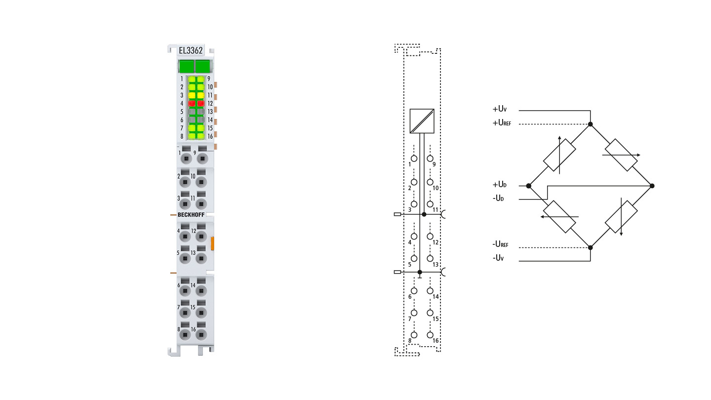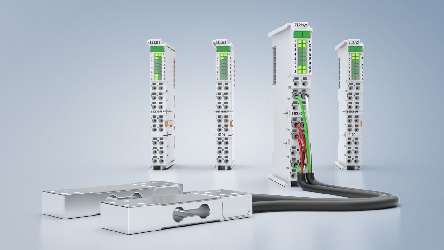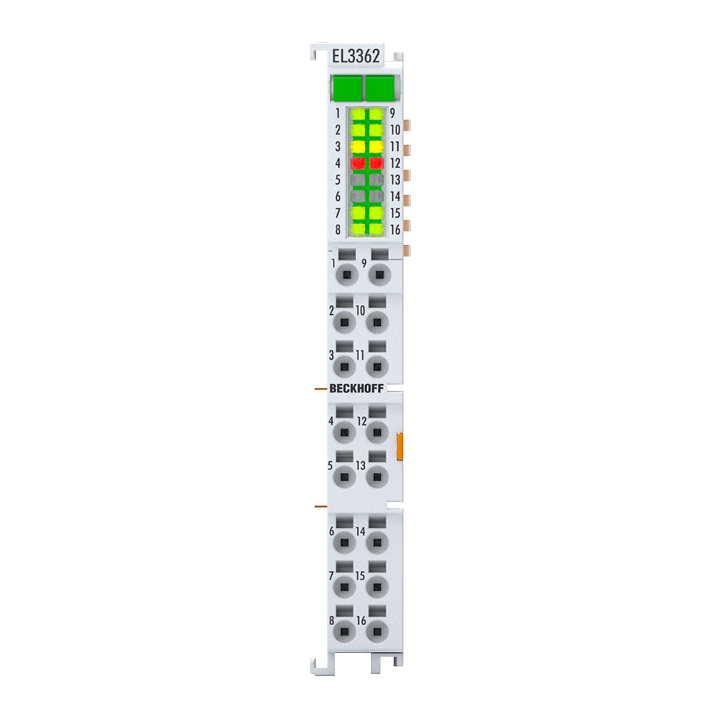
The EL3362 analog input terminal enables the direct connection of resistor bridges (strain gauges) or load cells using the 4-wire or 6-wire connection technique. It processes the ratio of the bridge voltage UD to the supply voltage UREF and outputs the final load value as a process value based on the terminal settings. This enables precise recording of weights, torques, and vibrations with a sampling rate of 10,000 samples per second.
The integrated bridge supply is generated from the 24 V of the power contacts, with a choice between 5 V and 10 V DC in the configuration.
The terminal also has a combined digital input/output per channel; the function for the digital connection point must be specified in the configuration. The digital input can be used for functions such as taring. The digital output can be switched on the basis of local evaluations in the terminal depending on the measured value of the resistance bridge.
Product status:
product announcement | estimated market release 2nd quarter 2025
Product information
| Technical data | Analog input |
|---|---|
| Number of inputs | 4, for 2 resistor bridge in full bridge technology |
| Function | resistance bridge, strain gauge (SG), voltage measurement |
| Wiring | 4-wire, 6-wire |
| Ground reference (input) | differential |
| Max. sampling rate | 10 kSps |
| Sampling type | simultaneous |
| Internal resistance | > 1 MΩ |
| Supported nominal sensitivity | 0.5…320 mV/V |
| Sensor supply | 10 V DC from power contacts |
| Measuring range, nominal | Uref: ±12 V | UD: ±4 V |
| Measuring range, technical | Uref: ±12,84 V | UD: ±4,28 V |
| Resolution | 24 bit |
| Measurement error/uncertainty | < ±0.05% |
| Electrical isolation channel/channel | no |
| Operating temperature | 0…55°C |
| Technical data | Digital input |
|---|---|
| Number of inputs | max. 1 |
| Wiring | 1-wire |
| “0” signal voltage | 0…1.5 V |
| “1” signal voltage | 2.5…30 V |
| Input current | typ. 3 mA |
| Operating temperature | 0…55°C |
| Technical data | Digital output |
|---|---|
| Number of outputs | max. 1 |
| Wiring | 1-wire |
| Nominal voltage | 24 V DC (-15%/+20%) |
| Load type | ohmic, inductive |
| Max. output current | 0.5 A |
| Reverse voltage protection | yes |
| Operating temperature | 0…55°C |
| Technical data | General |
|---|---|
| Power supply | via the E-bus |
| Electrical isolation channel/bus | 707 V DC (type test) |
| Current consumption power contacts | typ. 30 mA, depends on UV |
| Current consumption E-bus | typ. 90 mA |
| Distributed clocks | – |
| Special features | integrated sensor supply, digital inputs/outputs, specification of the digital output depending on the analog measurement |
| Weight | approx. 50 g |
| Operating temperature | 0…55°C |
| Storage temperature | -25…+85°C |
| Relative humidity | 95%, no condensation |
| EMC immunity/emission | conforms to EN 61000-6-2/EN 61000-6-4 |
| Vibration/shock resistance | conforms to EN 60068-2-6/EN 60068-2-27 |
| Protect. rating/installation pos. | IP20/variable |
| Approvals/markings | CE |
| Housing data | EL-12-16pin |
|---|---|
| Design form | HD (High Density) housing with signal LEDs |
| Material | polycarbonate |
| Dimensions (W x H x D) | 12 mm x 100 mm x 68 mm |
| Installation | on 35 mm DIN rail, conforming to EN 60715 with lock |
| Side by side mounting by means of | double slot and key connection |
| Marking | labeling of the BZxxx series |
| Wiring | solid conductors (s): direct plug-in technique; fine-stranded conductors (st) and ferrule (f): spring actuation by screwdriver |
| Connection cross-section | s*: 0.08…1.5 mm², st*: 0.25…1.5 mm², f*: 0.14…0.75 mm² |
| Connection cross-section AWG | s*: AWG28…16, st*: AWG22…16, f*: AWG26…19 |
| Stripping length | 8…9 mm |
| Current load power contacts | Imax: 10 A |
*s: solid wire; st: stranded wire; f: with ferrule
Loading content ...
Loading content ...
Loading content ...
© Beckhoff Automation 2025 - Terms of Use
