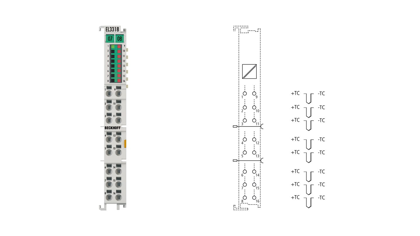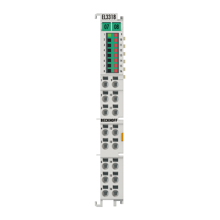
The EL3318 analog input terminal allows eight thermocouples to be connected directly and is thus particularly suitable for space-saving use in control cabinets. The EtherCAT Terminal circuit can operate thermocouple sensors using the 2-wire technique. A microprocessor handles linearization across the whole temperature range, which is freely selectable. The error LEDs indicate a broken wire. Compensation for the cold junction is made through an internal temperature measurement at the terminal. The EL3318 can also be used for mV measurement.
The HD EtherCAT Terminals (High Density) with increased packing density feature 16 connection points in the housing of a 12 mm terminal block.
Product status:
regular delivery
Product information
| Technical data | EL3318 |
|---|---|
| Number of inputs | 8 |
| Power supply | via the E-bus |
| Distributed clocks | – |
| Input filter limit frequency | typ. 1 kHz |
| Connection method | 2-wire |
| Conversion time | approx. 2.5 s up to 20 ms, depending on configuration and filter setting, default: approx. 250 ms |
| Voltage measurement | ±30/±60/±75 mV |
| Resolution | 16 bit, representation adjustable: 0.1/0.01°C or 1/2/4 µV per digit |
| Temperature measurement (thermocouple) | type B, C, E, J, K, L, N, R, S, T, U (default setting: type K) |
| Measurement uncertainty (temperature measurement) | at 23 °C ambient temperature, with internal cold junction, according type: B: ±6.3°C; C: ±4.9°C; E: ±3.1°C; J: ±3.2°C; K: ±3.0°C; L: ±3.1°C; N: ±3.4°C; R: ±5.2°C; S: ±5.4°C; T: ±3.3°C; U: ±3.2°C; for further details see documentation |
| Measurement uncertainty (voltage measurement) | at ±75 mV, 23°C ambient temperature: < ±0.096% (relative to full scale value) |
| Electrical isolation | 500 V (E-bus/signal voltage) |
| Current consumption E-bus | typ. 210 mA |
| Current consumption power contacts | – |
| Special features | channel by channel wire break detection, internal and external cold junction, firmware filter adjustable |
| Operating temperature | -25…+60°C |
| Storage temperature | -40…+85°C |
| Relative humidity | 95%, no condensation |
| Weight | approx. 70 g |
| Vibration/shock resistance | conforms to EN 60068-2-6/EN 60068-2-27 |
| EMC immunity/emission | conforms to EN 61000-6-2/EN 61000-6-4 |
| Approvals/markings | CE, CCC, UL, ATEX, IECEx, cFMus |
| Protect. rating/installation pos. | IP20/variable |
| Ex marking | ATEX: II 3G Ex ec IIC T4 Gc IECEx: Ex ec IIC T4 Gc cFMus: Class I, Division 2, Groups A, B, C, D Class I, Zone 2, AEx ec IIC T4 Gc |
| Housing data | EL-12-16pin |
|---|---|
| Design form | HD (High Density) housing with signal LEDs |
| Material | polycarbonate |
| Dimensions (W x H x D) | 12 mm x 100 mm x 68 mm |
| Installation | on 35 mm DIN rail, conforming to EN 60715 with lock |
| Side by side mounting by means of | double slot and key connection |
| Marking | labeling of the BZxxx series |
| Wiring | solid conductors (s): direct plug-in technique; fine-stranded conductors (st) and ferrule (f): spring actuation by screwdriver |
| Connection cross-section | s*: 0.08…1.5 mm², st*: 0.25…1.5 mm², f*: 0.14…0.75 mm² |
| Connection cross-section AWG | s*: AWG28…16, st*: AWG22…16, f*: AWG26…19 |
| Stripping length | 8…9 mm |
| Current load power contacts | Imax: 10 A |
*s: solid wire; st: stranded wire; f: with ferrule
Loading content ...
Loading content ...
Loading content ...
Loading content ...
© Beckhoff Automation 2025 - Terms of Use
