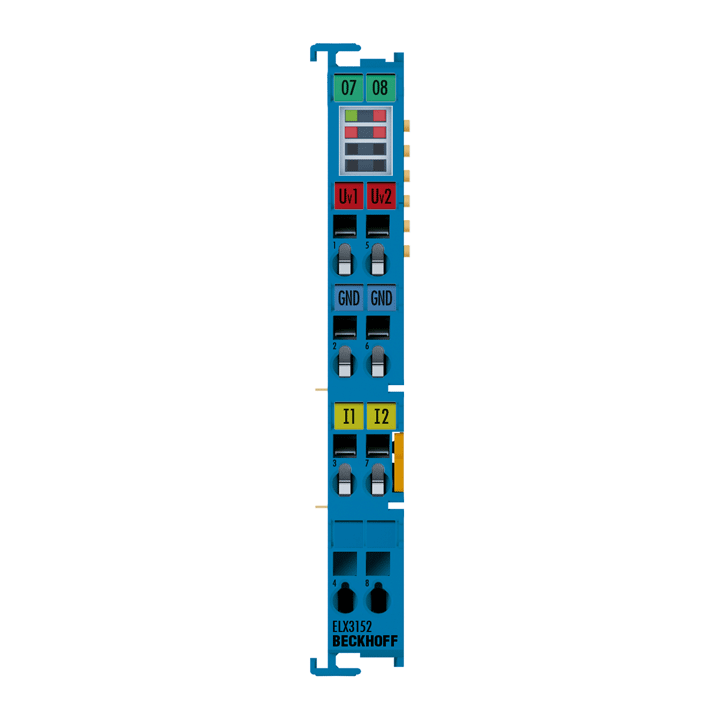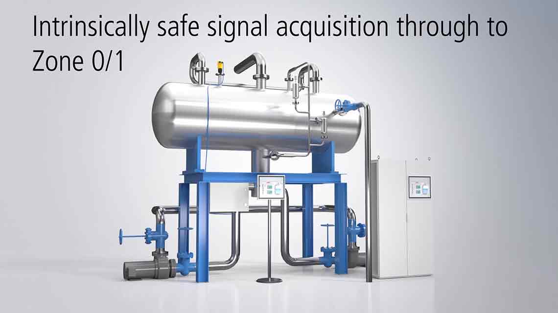
The ELX3152 analog input terminal allows the direct connection of intrinsically safe field devices located in hazardous areas classified zone 0/20 or 1/21. It supplies measuring transducers located in the field and transmits their analog measuring signals electrically isolated to the automation device. The measuring range can be switched between 0...20 mA and 4...20 mA by software. With a technical measuring range of ±107% of the nominal range, the terminal also supports commissioning with sensor values in the limit range and evaluation according to NAMUR NE43. The error LEDs indicate an overload condition and wire breakage.
EtherCAT terminals of the ELX series must always be operated in conjunction with the ELX9560 power supply terminal. This terminal generates an electrically isolated output voltage (24 V EX) from the input voltage (24 V DC) for supplying the subsequent ELX terminals. If a new power supply is required, the combination of an ELX9410 and an ELX9560 can be used so that further ELX terminals can be added. The ELX terminal string must be terminated with one ELX9012 or two ELX9410.
Product status:
regular delivery
Product information
| Technical data | ELX3152 |
|---|---|
| Technology | current input |
| Signal current | 0/4…20 mA |
| Number of inputs | 2 (single-ended) |
| Connection method | 2-, 3-wire |
| Resolution | 16 bit (incl. sign) |
| Measurement error/uncertainty | < ±0.3% (relative to full scale value) |
| Measuring resistance | typ. 100 Ω |
| Input filter limit frequency | 5 kHz |
| Conversion time | typ. 1 ms |
| Supply voltage electronics | 24 V DC (via power contacts), ELX9560 power supply |
| Current consumption power contacts | typ. 10 mA + load |
| Current consumption E-bus | typ. 85 mA |
| Distributed clocks | yes |
| Special features | standard and compact process image, activatable FIR/IIR filters, limit value monitoring, NE43 NAMUR |
| Weight | approx. 60 g |
| Operating temperature | -25…+60°C |
| Storage temperature | -40…+85°C |
| Relative humidity | 95%, no condensation |
| Vibration/shock resistance | conforms to EN 60068-2-6/EN 60068-2-27 |
| EMC immunity/emission | conforms to EN 61000-6-2/EN 61000-6-4 |
| Protect. rating/installation pos. | IP20/see documentation |
| Approvals/markings | CE, UL, ATEX, IECEx, cFMus, CCC |
| Ex marking | ATEX: II 3(1)G Ex ec [ia Ga] IIC T4 Gc II (1)D [Ex ia Da] IIIC I (M1) [Ex ia Ma] I IECEx: Ex ec [ia Ga] IIC T4 Gc [Ex ia Da] IIIC [Ex ia Ma] I cFMus: AIS Class I, II, III, Division 1, Groups A thru G Class I, Division 2, Groups A, B, C, D Class I, Zone 2, AEx ec [ia Ga] IIC T4 Gc [AEx ia Da] IIIC T4 |
| Housing data | ELX-12-8pin |
|---|---|
| Design form | compact terminal housing with signal LEDs |
| Material | polycarbonate, blue |
| Dimensions (W x H x D) | 12 mm x 100 mm x 68 mm |
| Installation | on 35 mm DIN rail, conforming to EN 60715 with lock |
| Side by side mounting by means of | double slot and key connection |
| Marking | labeling of the BZxxxx series |
| Wiring | solid conductor (s), flexible conductor (st) and ferrule (f): spring actuation by screwdriver |
| Connection cross-section | s*: 0.08…2.5 mm², st*: 0.08…2.5 mm², f*: 0.14…1.5 mm² |
| Connection cross-section AWG | s*: AWG28…14, st*: AWG28…14, f*: AWG26…16 |
| Stripping length | 8…9 mm |
| Power contacts | 2 blade/spring contacts |
*s: solid wire; st: stranded wire; f: with ferrule
Loading content ...
Loading content ...
Loading content ...
Loading content ...
© Beckhoff Automation 2025 - Terms of Use


