Optimized control of proportional valves with PWM
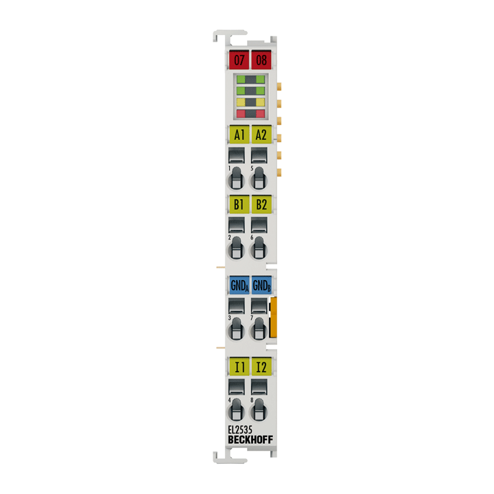
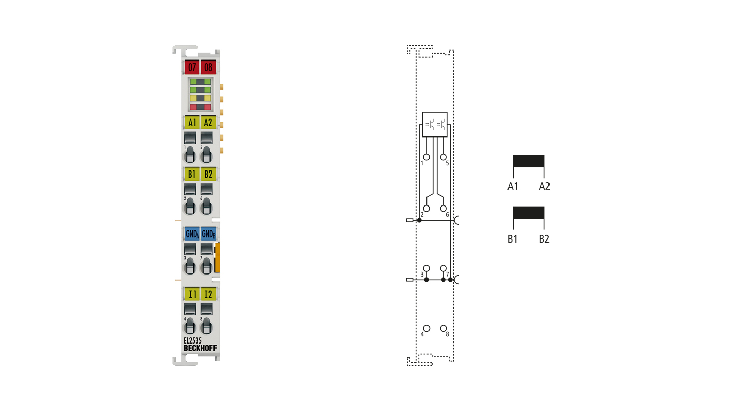
The EL2535-xxxx output terminals are specially designed for the precise control of single and double-coil proportional valves and proportional solenoid valves. They regulate the output current through pulse width modulation (PWM) of the supply voltage and are electrically isolated from the E-bus. The current values (0 to maximum output current) are specified by the automation device through a 16-bit value. The output stages are protected against overload and short circuit. Each EtherCAT pulse width current terminal contains two channels whose signal state is indicated by LEDs. The light emitting diodes simplify local diagnosis by displaying typical load and wiring faults.
Special properties:
- 2 PWM outputs with push-pull output stage
- suitable for inductive loads > 1 mH
- max. output current ±50 mA per channel at 24 V DC nominal voltage
Product status:
regular delivery
Product information
| Technical data | EL2535-0050 |
|---|---|
| Connection technology | PWM output, push-pull outputs |
| Number of outputs | 2 |
| Nominal voltage | 24 V DC (-15%/+20%) |
| Load type | inductive > 1 mH |
| Distributed clocks | – |
| Max. output current | ±50 mA |
| Short-circuit current | < 500 mA typ. |
| PWM clock frequency | 30 kHz default |
| Duty factor | 0…100% (current-controlled) |
| Resolution | 10 bit |
| Reverse voltage protection | yes |
| Current consumption E-bus | typ. 110 mA |
| Current consumption power contacts | typ. 30 mA + load |
| Bit width in the process image | 48 inputs/outputs: 2 x 16 bit data, 2 x 8 bit control/status |
| Electrical isolation | 500 V (E-bus/field potential) |
| Special features | 2 digital 24 V inputs |
| Weight | approx. 50 g |
| Operating temperature | 0…55°C |
| Storage temperature | -25…+85°C |
| Relative humidity | 95%, no condensation |
| Vibration/shock resistance | conforms to EN 60068-2-6/EN 60068-2-27 |
| EMC immunity/emission | conforms to EN 61000-6-2/EN 61000-6-4 |
| Protect. rating/installation pos. | IP20/see documentation |
| Pluggable wiring | for all ESxxxx terminals |
| Approvals/markings | CE, CCC, UL, ATEX, IECEx |
| Ex marking | ATEX: II 3 G Ex ec IIC T4 Gc IECEx: Ex ec IIC T4 Gc cFMus: Class I, Division 2, Groups A, B, C, D Class I, Zone 2, AEx ec IIC T4 Gc |
| Housing data | EL-12-8pin | ES-12-8pin |
|---|---|---|
| Design form | compact terminal housing with signal LEDs | terminal housing with pluggable wiring level |
| Material | polycarbonate | |
| Dimensions (W x H x D) | 12 mm x 100 mm x 68 mm | |
| Installation | on 35 mm DIN rail, conforming to EN 60715 with lock | |
| Side by side mounting by means of | double slot and key connection | |
| Marking | labeling of the BZxxxx series | |
| Wiring | solid conductor (s), flexible conductor (st) and ferrule (f): spring actuation by screwdriver | |
| Connection cross-section | s*: 0.08…2.5 mm², st*: 0.08…2.5 mm², f*: 0.14…1.5 mm² | s*: 0.08…1.5 mm², st*: 0.08…1.5 mm², f*: 0.14…1.5 mm² |
| Connection cross-section AWG | s*: AWG28…14, st*: AWG28…14, f*: AWG26…16 | s*: AWG28…16, st*: AWG28…16, f*: AWG26…16 |
| Stripping length | 8…9 mm | 9…10 mm |
| Current load power contacts | Imax: 10 A | |
*s: solid wire; st: stranded wire; f: with ferrule
Loading content ...
Loading content ...
Loading content ...
Loading content ...
Loading content ...
© Beckhoff Automation 2025 - Terms of Use


