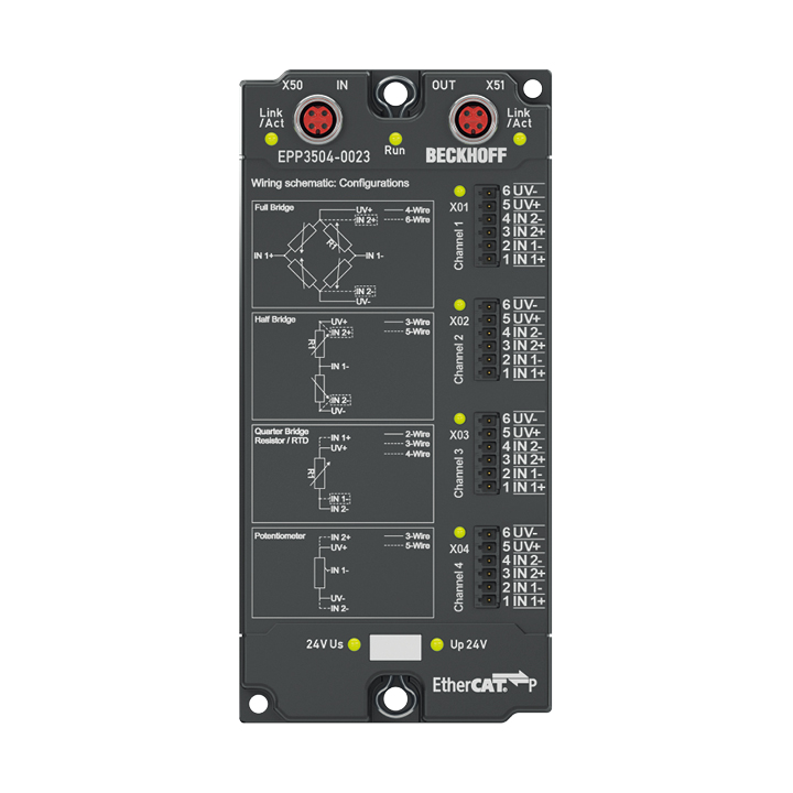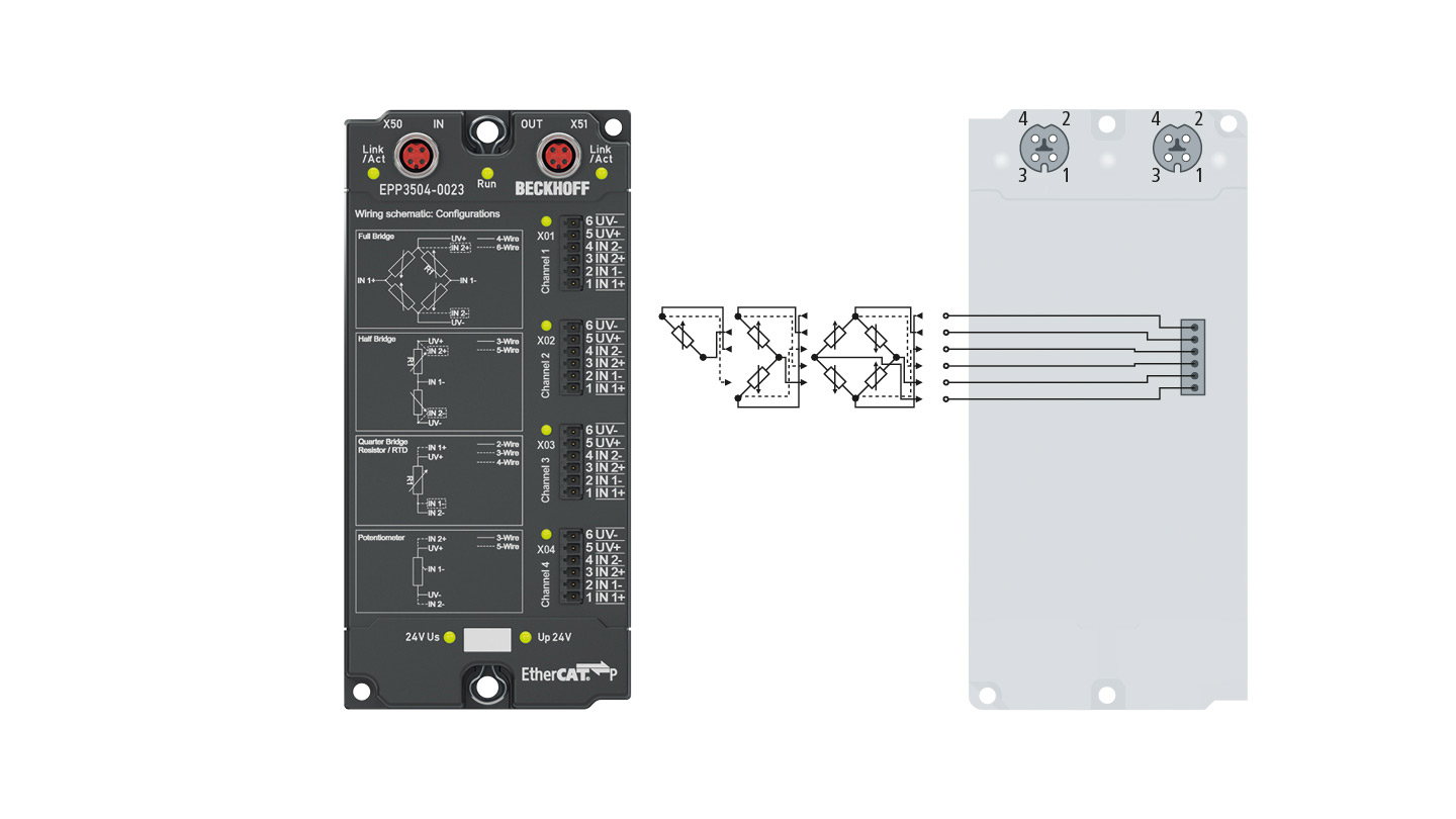
The EPP3504-0023 EtherCAT P Box is designed for the evaluation of measuring bridges in full-bridge, half-bridge and quarter-bridge configuration. It also supports the potentiometer, Pt1000 (RTD) and ±10 V measuring ranges. It is derived from the ELM3504 EtherCAT Terminal and features a sampling rate of 10,000 sps, internal switchable supplementary resistors, and an integrated, parametrizable bridge supply. It also features the same technological properties as the ELM3x0x terminals – i.e., all parameters can be set via EtherCAT using the CoE directory. The EPP3504-0023 is designed for use in close proximity to the measurement site in a protected environment and is therefore equipped with IP20 bridge connections.
Product status:
regular delivery
Product information
| System data | |
|---|---|
| Strain gauge | quarter bridge (1000/350/120 Ω), half bridge (±16/8/4/2 mV/V), full bridge (±32/8/4/2 mV/V), internal bridge completion and supply adjustable 0…5 V (2-/3-/4-/5-/6-wire connection), shunt calibration |
| Voltage measurement | ±10 V, ±80 mV, 0…10 V |
| Potentiometer measurement | potentiometer ≥ 1 kΩ, supply integrated and adjustable 0…5 V |
| Temperature measurement (RTD) | Pt1000 |
| Technical data | EPP3504-0023 |
|---|---|
| Protocol | EtherCAT |
| Bus interface | 2 x M8 socket, P-coded, shielded |
| Technology | resistor bridge, strain gauge |
| Number of channels | 4 |
| Input connections | connector with spring-loaded system |
| Connection method | 2-/3-/4-/5-/6-wire |
| Connection type | push-in, service plug 6-pin |
| Max. sampling rate | max. 100 µs/10 ksps (per channel, simultaneously) |
| Oversampling factor | n = 1…100 selectable (max. 10 ksamples/s) |
| Voltage measurement | ±10 V, ±80 mV, 0…10 V |
| Resolution | 24 bit (incl. sign) |
| Signal type | differential |
| Internal resistance | > 4 MΩ |
| Measurement error/uncertainty | typ. < ±1000 ppm/±0.1% in some measuring ranges, relative to the respective full scale value, see documentation |
| Nominal voltage | 24 V DC (-15%/+20%) |
| Temperature coefficient | up to typ. < 1 ppm/K in some measuring ranges, see documentation |
| Functional diagnostics | yes |
| Connection diagnostics | broken wire/short circuit |
| Distributed clocks | yes, accuracy << 1 µs |
| Current consumption from US | typ. 150 mA |
| Current consumption from UP | none (only diagnostics LED, sensors are supplied from Us) |
| Electrical isolation channel/channel | no |
| Electrical isolation channel/bus | 707 V DC (type test) |
| Electrical isolation channel/SGND | 707 V DC (type test) |
| Thermal dissipation | typ. 3 W |
| Special features | ExtendedRange 107%, free numeric filter, TrueRMS, integrator/differentiator, non-linear scaling, PeakHold |
| Weight | approx. 250 g |
| Operating/storage temperature | 0…+55°C/-25…+85°C |
| Vibration/shock resistance | conforms to EN 60068-2-6/EN 60068-2-27 |
| EMC immunity/emission | conforms to EN 61000-6-2/EN 61000-6-4 |
| Protect. rating/installation pos. | IP20/variable conforms to EN 60529 (see documentation) |
| Approvals/markings | CE, UL (in preparation) |
| Housing data | 16 x M8, 8 x M12 |
|---|---|
| Dimensions (W x H x D) | 60 mm x 126 mm x 26.5 mm |
| Material | PA6 (polyamide) |
| Installation | 2 fixing holes 3.5 mm diameter for M3; 2 fixing holes 4.5 mm diameter for M4 |
Loading content ...
Loading content ...
Loading content ...
Loading content ...
Loading content ...
Loading content ...
© Beckhoff Automation 2024 - Terms of Use


