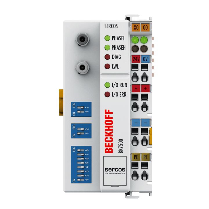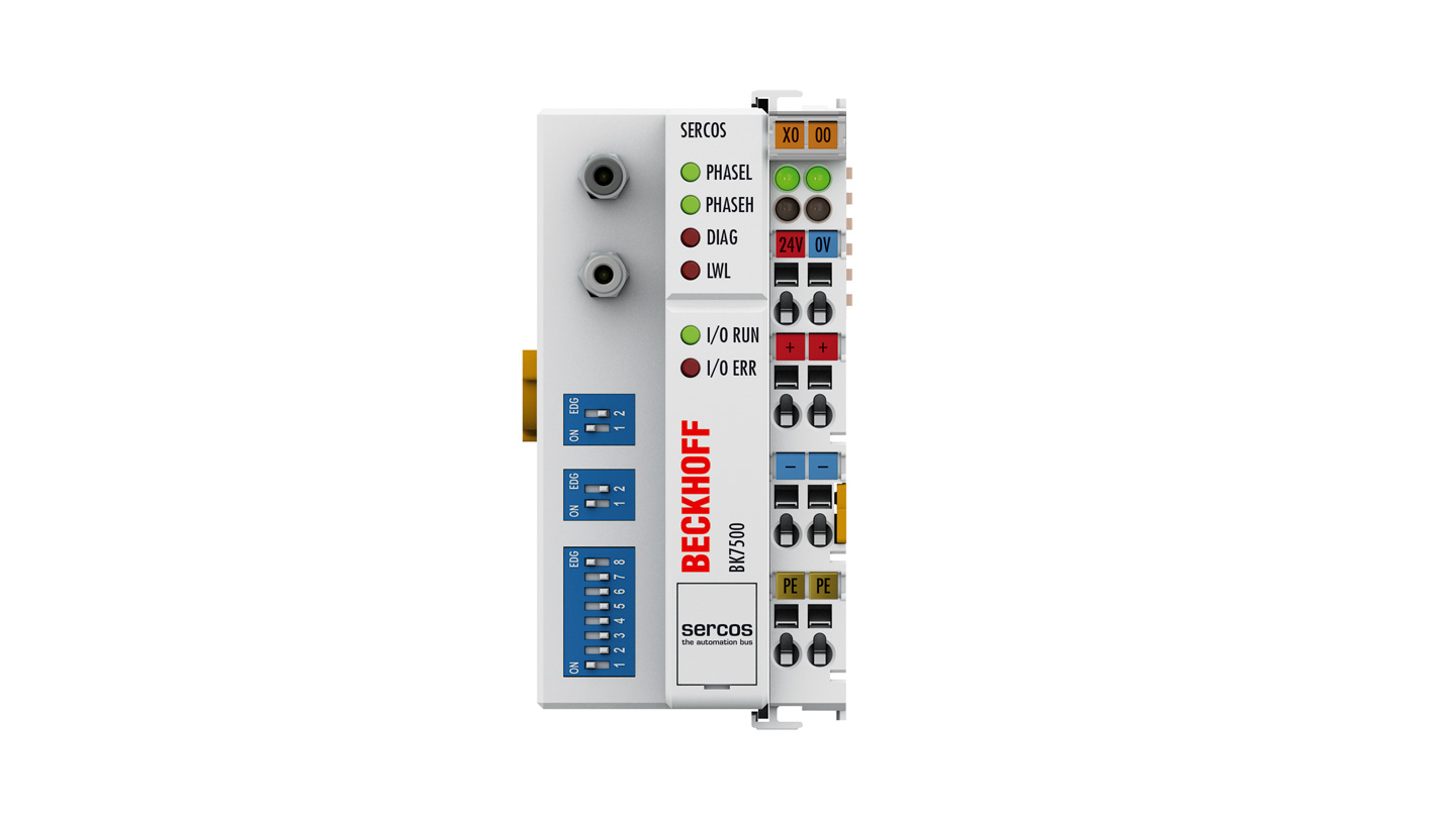
The BK7500 Bus Coupler connects the SERCOS bus system with the electronic terminal blocks, which can be extended in modular fashion. One unit consists of one Bus Coupler, any number from 1 to 64 terminals and one end terminal. The Bus Coupler recognizes the connected terminals and automatically generates the affiliations of the inputs/outputs to the bytes of the process image.
SERCOS is a fiber optic bus that was developed for use in drive technology as a digital drive interface for drives. SERCOS is an open fieldbus system, which since 1995 has been subject to the international standard IEC 61491 for numerically controlled machines. It is widely used in the drive technology sector.
The bus consists of a master and of a number of slaves. In SERCOS, most of the slaves are drive amplifiers. The bus topology is a ring system, in which it is possible to operate up to 254 stations. The transmission speed is 2 and 4 Mbaud. There are basically three types of telegrams. The master SYNC telegram is received by all the slaves at the same time, and is used for synchronization. The master data telegram is also received by all the slaves, and contains the cyclic data and the service data. The slaves send their data in what is known as a drive telegram.
Parameterization can also be carried out via the SERCOS interface.
Product status:
regular delivery (not recommended for new projects) | recommended alternative: BK7520
Product information
| Technical data | BK7500 |
|---|---|
| Number of Bus Terminals | 64 |
| Max. number of bytes fieldbus | 32 byte input/32 byte output for the cyclic interface (depending on the master) |
| Digital peripheral signals | 256 inputs/outputs |
| Analog peripheral signals | 128 inputs/outputs |
| Configuration possibility | via KS2000 |
| Data transfer rates | 2/4 Mbaud, adjustable by means of configuration switch |
| Bus interface | FSMA standard, IEC 872-2 |
| Data transfer medium | 1,000 µm plastic fiber optic |
| Power supply | 24 V DC (-15%/+20%) |
| Input current | 70 mA + (total K-bus current)/4, 500 mA max. |
| Starting current | 2.5 x continuous current |
| Recommended fuse | ≤ 10 A |
| Current supply K-bus | 1750 mA |
| Power contacts | max. 24 V DC/max. 10 A |
| Electrical isolation | 500 V (power contact/supply voltage/fieldbus) |
| Distance between stations | 40 m plastic fiber optic |
| Weight | approx. 170 g |
| Operating/storage temperature | 0…+55°C/-25…+85°C |
| Relative humidity | 95%, no condensation |
| Vibration/shock resistance | conforms to EN 60068-2-6/EN 60068-2-27 |
| EMC immunity/emission | conforms to EN 61000-6-2/EN 61000-6-4 |
| Protect. rating/installation pos. | IP20/variable |
| Approvals/markings | CE, UL, ATEX, IECEx |
| Ex marking | ATEX: II 3 G Ex ec IIC T4 Gc IECEx: Ex ec IIC T4 Gc |
| Housing data | BKxxxx, BCxxxx |
|---|---|
| Design form | compact terminal housing with signal LEDs |
| Material | polycarbonate |
| Dimensions (W x H x D) | 51 mm x 100 mm x 69 mm |
| Installation | on 35 mm DIN rail, conforming to EN 60715 with lock |
| Side by side mounting by means of | double slot and key connection |
| Marking | labeling of the BZxxx series |
| Wiring | solid conductor (s), flexible conductor (st) and ferrule (f): spring actuation by screwdriver |
| Connection cross-section | s*: 0.08…2.5 mm², st*: 0.08…2.5 mm², f*: 0.14…1.5 mm² |
| Stripping length | 8…9 mm |
| Current load power contacts | Imax: 10 A |
*s: solid wire; st: stranded wire; f: with ferrule
Loading content ...
Loading content ...
Loading content ...
© Beckhoff Automation 2024 - Terms of Use


