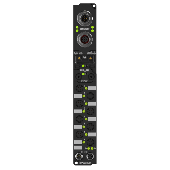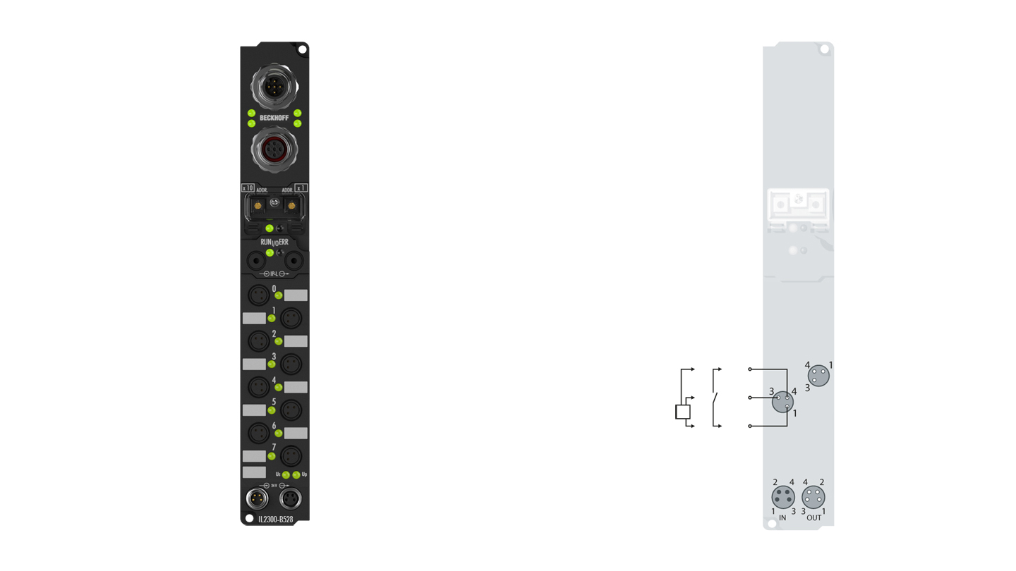
The IL2300Bxxx Coupler Box module combines four digital inputs with 3.0 ms input filter and four digital outputs in one device. The outputs handle load currents of up to 0.5 A, are short-circuit proof and protected against inverse polarity. The state of each signal is indicated by means of light emitting diodes. The signals are connected via 8 mm snap type connectors.
Product status:
service phase | Possibly with other technical features or equipment in case of a service order or repair. Recommended alternative: IL2301-B528
Product information
| Technical data digital inputs/outputs | IL2300-Bxxx |
|---|---|
| Specification | EN 61131-2, type 2 |
| Number of channels | 4 inputs + 4 outputs |
| Input/output connections | 8 mm, snap type |
| Input filter | 3.0 ms |
| “0” signal voltage | -3…+5 V |
| “1” signal voltage | 11…30 V, 6 mA input current (EN 61131-2, type 2) |
| Sensor supply | from control voltage, max. 0.5 A, short-circuit proof in total |
| Load type | ohmic, inductive, lamp load |
| Rated load voltage | 24 V DC (-15%/+20%) |
| Max. output current | 0.5 A per channel, individually short-circuit proof |
| Short-circuit current | typ. 1.5 A |
| Auxiliary power current | typ. 20 mA |
| Current consumption from US | see documentation |
| Power supply connection | feed: 1 x M8 male socket, 4-pin, a-coded; downstream connection: 1 x M8 female socket, 4-pin, a-coded |
| Bit width in the process image | 4 inputs + 4 outputs |
| Electrical isolation | channels/control voltage: no, between the channels: no, control voltage/fieldbus: depends on the bus system |
| Special features | IP-Link coupler |
| Operating/storage temperature | 0…+55°C/-25…+85°C |
| Vibration/shock resistance | conforms to EN 60068-2-6/EN 60068-2-27 |
| EMC immunity/emission | conforms to EN 61000-6-2/EN 61000-6-4 |
| Protect. rating/installation pos. | IP65/66/67 (conforms to EN 60529)/variable |
| Approvals/markings | CE, UL |
| Technical data | IL2300-B528 |
|---|---|
| Extension modules | max. 120 with max. 512 byte input and 512 byte output data |
| Digital peripheral signals | max. 960 inputs and 960 outputs |
| Analog peripheral signals | max. 252 inputs and 252 outputs |
| DeviceNet type | communications adapter |
| Configuration possibility | through KS2000 or the controller (explicit messaging) |
| Data transfer rates | automatic detection up to 500 kbaud |
| Bus interface | 1 x M12 plug, 5-pin, 1 x M12 socket, 5-pin (tee-connector integrated) |
| Data transfer medium | shielded copper cable, with power supply, typ. 2 x 2 x 0.25 mm² |
| Power supply | control voltage: 24 V DC (-15%/+20%); load voltage: according to I/O type |
| Power supply connection | feed: 1 x M8 male socket, 4-pin, a-coded; downstream connection: 1 x M8 female socket, 4-pin, a-coded |
| Box supply current | 45 mA + current consumption of sensors, max. 0.5 A |
| Auxiliary power current | according to I/O type |
| Electrical isolation | control voltage/fieldbus: 500 V, control voltage/inputs or outputs: according to I/O type |
| Distance between stations | 500 m 250 m 100 m |
| I/O communication types | bit strobe, polling, cyclic, change of state |
| Operating/storage temperature | 0…+55°C/-25…+85°C |
| Vibration/shock resistance | conforms to EN 60068-2-6/EN 60068-2-27 |
| EMC immunity/emission | conforms to EN 61000-6-2/EN 61000-6-4 |
| Protect. rating/installation pos. | IP65/66/67 (conforms to EN 60529)/variable |
| Approvals/markings | CE, UL |
| Housing data | XXL housing |
|---|---|
| Dimensions (W x H x D) | 30 mm x 210 mm x 26.5 mm |
| Material | PA6 (polyamide) |
| Installation | 2 fixing holes 3.5 mm diameter for M3 |
Loading content ...
Loading content ...
© Beckhoff Automation 2024 - Terms of Use

