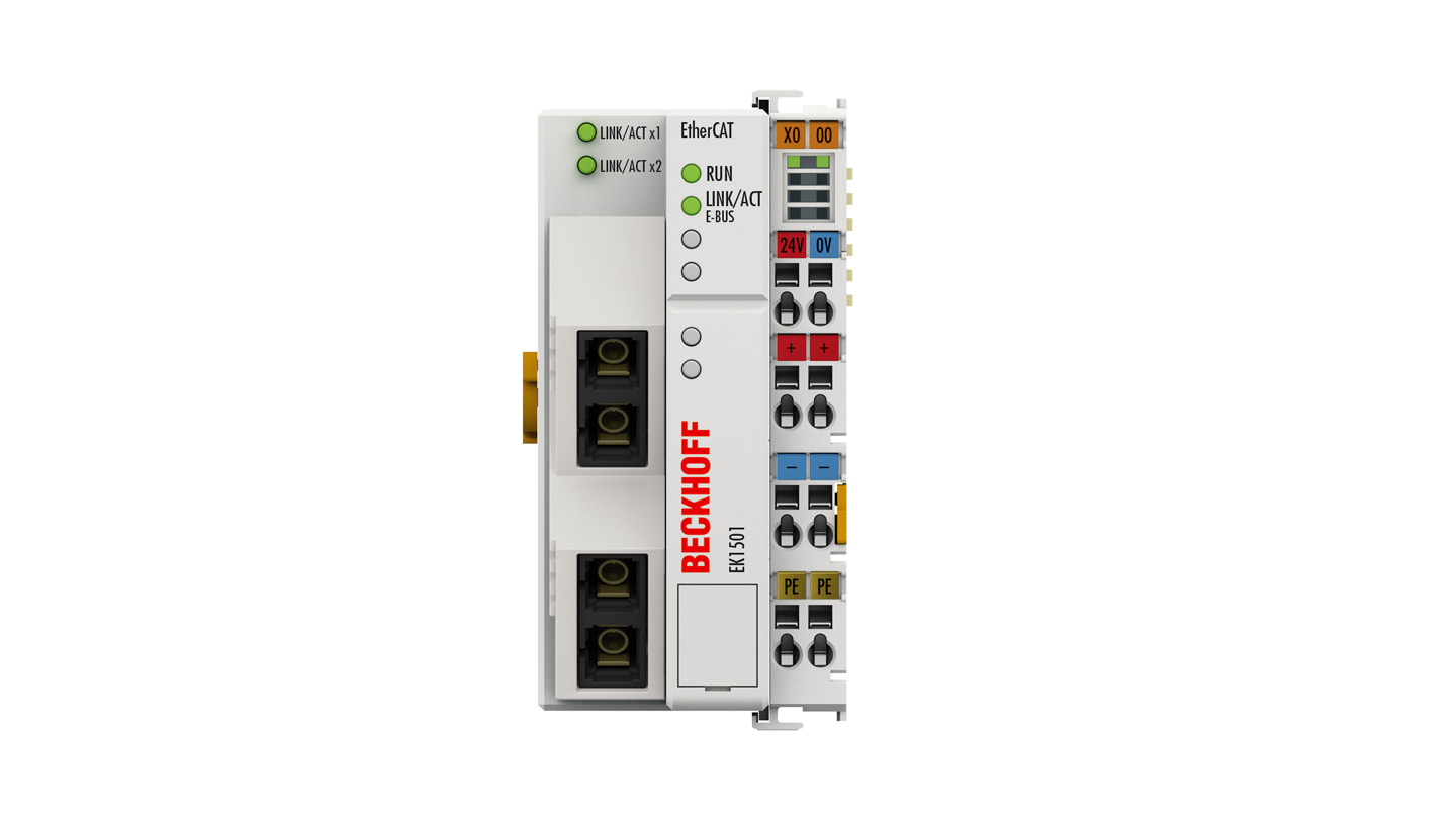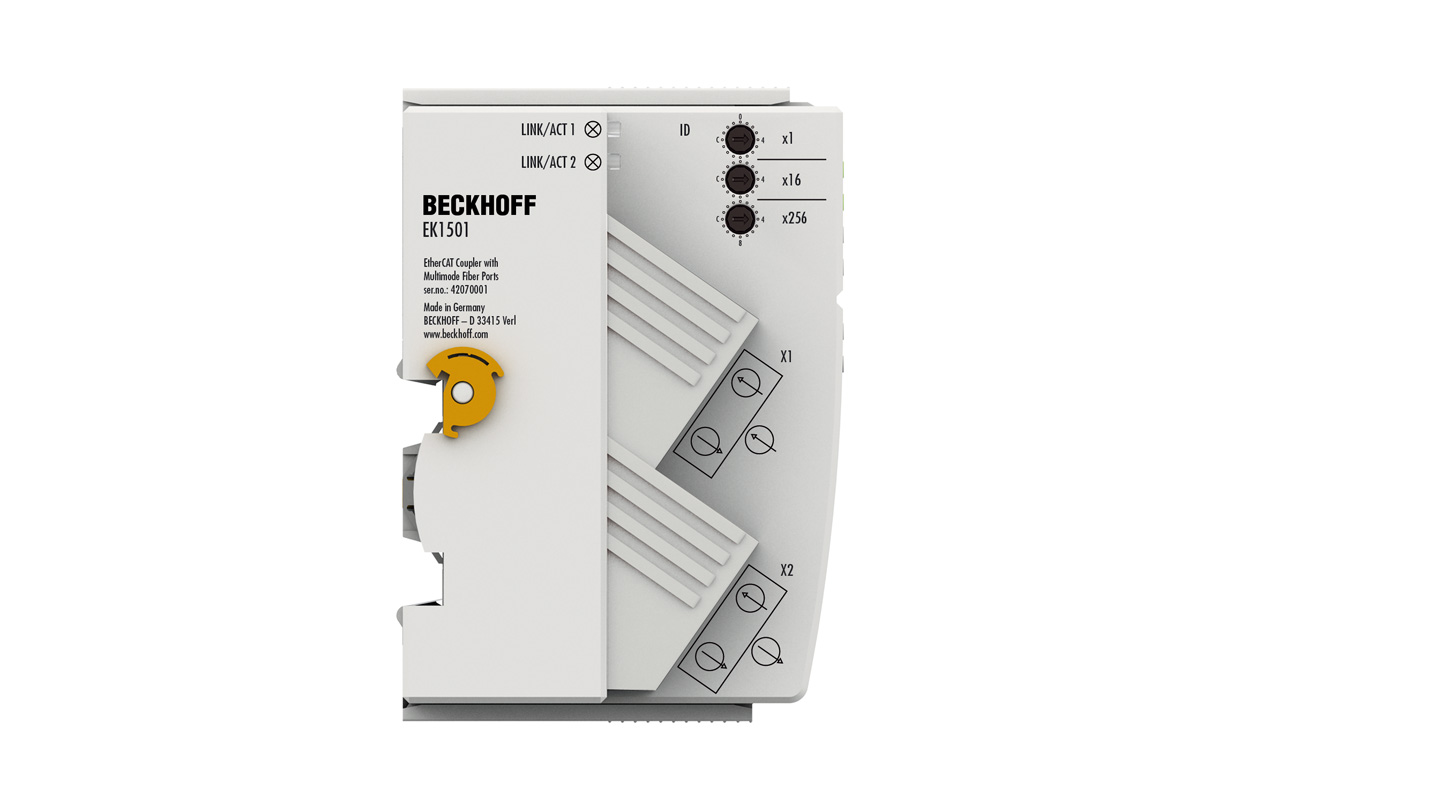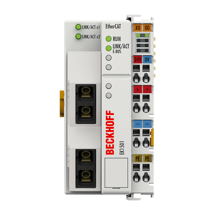
The EK1501 EtherCAT Coupler with multi-mode fiber-optic connection is the link between the EtherCAT protocol at fieldbus level and the EtherCAT Terminals. The coupler converts the passing telegrams from Ethernet 100BASE-FX to E-bus signal representation. A station consists of a coupler and any number of EtherCAT Terminals that are automatically detected and individually displayed in the process image.
Special features:
- connection technology 2 x multi-mode fiber-optic connection via SC duplex
- connection lengths up to 2 km
- 3 ID switches for implementing variable topologies
- number of EtherCAT Terminals in the overall system: up to 65,535
The EK1501 has two SC duplex sockets and three hexadecimal ID switches. The coupler is connected to the network via the upper Ethernet connection. The lower SC duplex socket may be used to connect further EtherCAT devices in the same segment. The multi-mode glass fiber connection enables distances of up to 2 km between two couplers. A group of EtherCAT components can be assigned a unique ID via the hexadecimal ID switches. This group can then be located at any position within the EtherCAT network. Variable topologies are therefore easily implementable. In addition, an EtherCAT junction or an EtherCAT extension can be used for the extension or for setting up a line or star topology.
The system and field supply, each 24 V DC, is provided directly at the coupler. The attached EtherCAT Terminals are supplied with the current required for communication from the supplied system voltage. The coupler can supply a maximum of 5 V and 2 A. Power feed terminals (e.g. EL9410) must be integrated if more current is required. The field supply is forwarded to the individual I/O components via the power contacts with up to 10 A.
Product status:
regular delivery
Product information
| Technical data | EK1501 |
|---|---|
| Task within EtherCAT system | coupling of EtherCAT Terminals (ELxxxx) to 100BASE-FX EtherCAT networks, with identity verification |
| Data transfer medium | multi-mode glass fiber 50/125 µm (MM) |
| Distance between stations | max. 2000 m (100BASE-FX) |
| Number of EtherCAT Terminals | up to 65,534 |
| Type/number of peripheral signals | max. 4.2 GB addressable I/O points |
| Number of configurable IDs | 4096 |
| Protocol | EtherCAT |
| Delay | approx. 1 µs |
| Data transfer rates | 100 Mbit/s |
| Bus interface | 2 x SC Duplex |
| Power supply | 24 V DC (-15%/+20%) |
| Current consumption from US | 130 mA + (∑ E-bus current/4) |
| Current consumption from UP | load |
| Current supply E-bus | 2000 mA |
| Power contacts | max. 24 V DC/max. 10 A |
| Electrical isolation | 500 V (power contact/supply voltage/Ethernet) |
| Weight | approx. 190 g |
| Operating temperature | -25…+60°C |
| Storage temperature | -40…+85°C |
| EMC immunity/emission | conforms to EN 61000-6-2/EN 61000-6-4 |
| Relative humidity | 95%, no condensation |
| Vibration/shock resistance | conforms to EN 60068-2-6/EN 60068-2-27 |
| Protect. rating/installation pos. | IP20/variable |
| Approvals/markings | CE, CCC, UL, ATEX, IECEx |
| Ex marking | ATEX: II 3 G Ex ec IIC T4 Gc IECEx: Ex ec IIC T4 Gc |
| Housing data | EK-51-8pin |
|---|---|
| Design form | compact terminal housing with signal LEDs |
| Material | polycarbonate |
| Dimensions (W x H x D) | 51 mm x 100 mm x 69 mm |
| Installation | on 35 mm DIN rail, conforming to EN 60715 with lock |
| Side by side mounting by means of | double slot and key connection |
| Marking | labeling of the BZxxx series |
| Wiring | solid conductor (s), flexible conductor (st) and ferrule (f): spring actuation by screwdriver |
| Connection cross-section | s*: 0.08…2.5 mm², st*: 0.08…2.5 mm², f*: 0.14…1.5 mm² |
| Connection cross-section AWG | s*: AWG28…14, st*: AWG28…14, f*: AWG26…16 |
| Stripping length | 8…9 mm |
| Current load power contacts | Imax: 10 A |
*s: solid wire; st: stranded wire; f: with ferrule
Loading content ...
Loading content ...
Loading content ...
Loading content ...
Loading content ...
© Beckhoff Automation 2025 - Terms of Use
