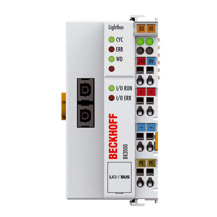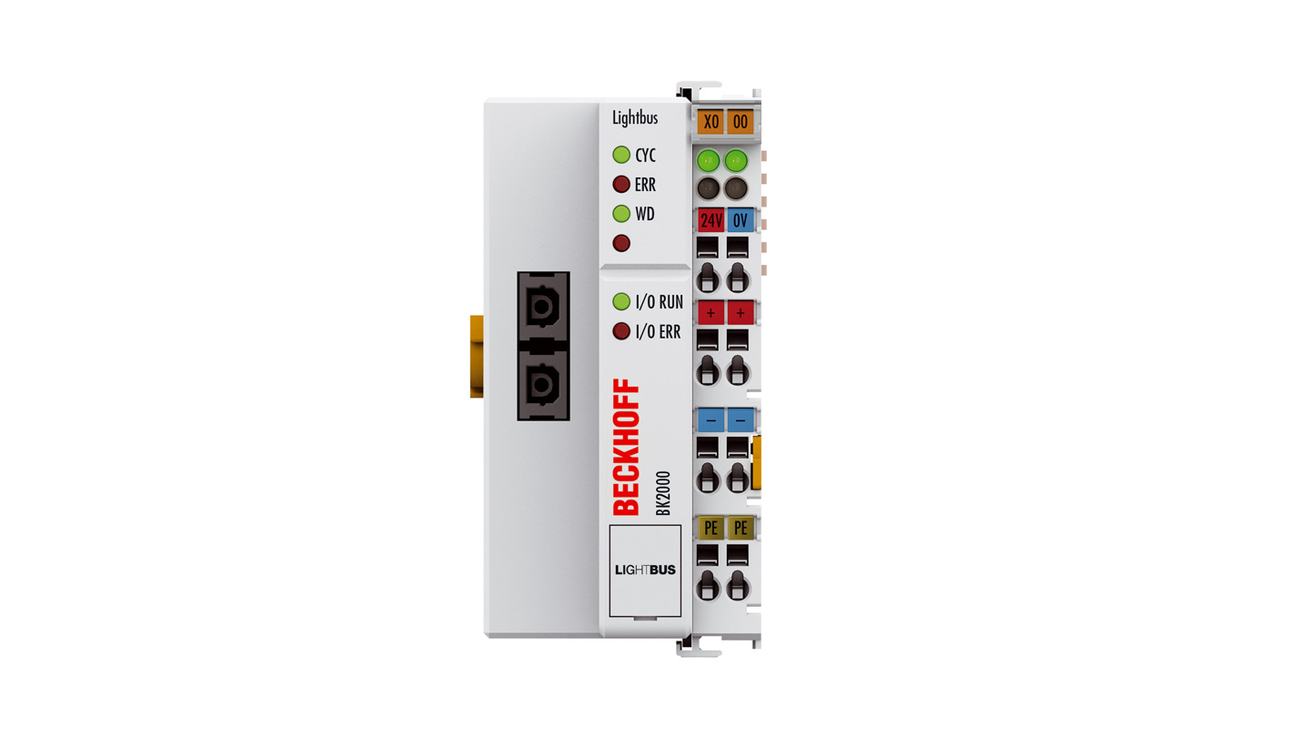
The BK2000 Bus Coupler connects the Lightbus system to the electronic terminal blocks, which can be expanded in modular fashion. One unit consists of one Bus Coupler, any number of up to 64 terminals and one end terminal.
The Bus Coupler recognizes the connected terminals and automatically generates the affiliations of the inputs/outputs to the bytes of the process image. The first input/output signal is inserted in the first bit of one byte (LSB), beginning from the left. The Bus Coupler inserts further signals in this byte. Inputs and outputs are clearly separated. The Bus Coupler automatically begins a further byte if the number of inputs or outputs exceeds 8 bits.
The Lightbus System is a rapid and safe serial fieldbus system. The Lightbus has a ring structure; up to 254 stations can be operated in a ring. Easy-to-operate standard fiber optic technology is used for data transmission, which represents excellent value. Thanks to an optimized, efficient telegram structure, the Lightbus achieves a very high user data transmission rate. For the exchange of 32 bit information 25 µs transmission time is required.
Thanks to the high-speed access method employed by the Lightbus, it is possible to access specific peripheral data and to read or write the required data only. Data is exchanged with the required priorities without producing any overhead.
Product status:
regular delivery (not recommended for new projects) | recommended alternative: BK2020
Product information
| Technical data | BK2000 |
|---|---|
| Number of Bus Terminals | 64 |
| Max. number of bytes fieldbus | 512 byte input and 512 byte output |
| Digital peripheral signals | 512 inputs/outputs |
| Analog peripheral signals | 128 inputs/outputs |
| Configuration possibility | via KS2000 or the controller |
| Data transfer rates | 2.5 Mbaud |
| Bus interface | 2 x standard fiber-optic connector Z1000 (plastic fiber), Z1010 (HCS fiber) |
| Data transfer medium | fiber-optic conductor: APF (plastic) fiber (1,000 µm) or HCS fiber (200 µm) |
| Power supply | 24 V DC (-15%/+20%) |
| Input current | 70 mA + (total K-bus current)/4, 500 mA max. |
| Starting current | approx. 2.5 x continuous current |
| Recommended fuse | ≤ 10 A |
| Current supply K-bus | 1750 mA |
| Power contacts | max. 24 V DC/max. 10 A |
| Electrical isolation | 500 V (power contact/supply voltage) |
| Distance between stations | 45 m for APF fiber, 300 m HCS fiber |
| Data transfer time | 0.26 ms in the case of 10 modules for 32 bit inputs and outputs each (without K-bus run-time) |
| Weight | approx. 150 g |
| Operating temperature | 0…55°C |
| Storage temperature | -25…+85°C |
| Relative humidity | 95%, no condensation |
| Vibration/shock resistance | conforms to EN 60068-2-6/EN 60068-2-27 |
| EMC immunity/emission | conforms to EN 61000-6-2/EN 61000-6-4 |
| Protect. rating/installation pos. | IP20/variable |
| Approvals/markings | CE, CCC, UL, ATEX, IECEx |
| Ex marking | ATEX: II 3 G Ex ec IIC T4 Gc IECEx: Ex ec IIC T4 Gc |
| Housing data | BKxxxx, BCxxxx |
|---|---|
| Design form | compact terminal housing with signal LEDs |
| Material | polycarbonate |
| Dimensions (W x H x D) | 51 mm x 100 mm x 69 mm |
| Installation | on 35 mm DIN rail, conforming to EN 60715 with lock |
| Side by side mounting by means of | double slot and key connection |
| Marking | labeling of the BZxxx series |
| Wiring | solid conductor (s), flexible conductor (st) and ferrule (f): spring actuation by screwdriver |
| Connection cross-section | s*: 0.08…2.5 mm², st*: 0.08…2.5 mm², f*: 0.14…1.5 mm² |
| Stripping length | 8…9 mm |
| Current load power contacts | Imax: 10 A |
*s: solid wire; st: stranded wire; f: with ferrule
Loading content ...
Loading content ...
Loading content ...
© Beckhoff Automation 2025 - Terms of Use


