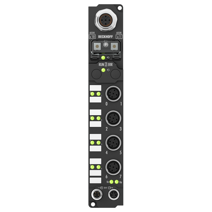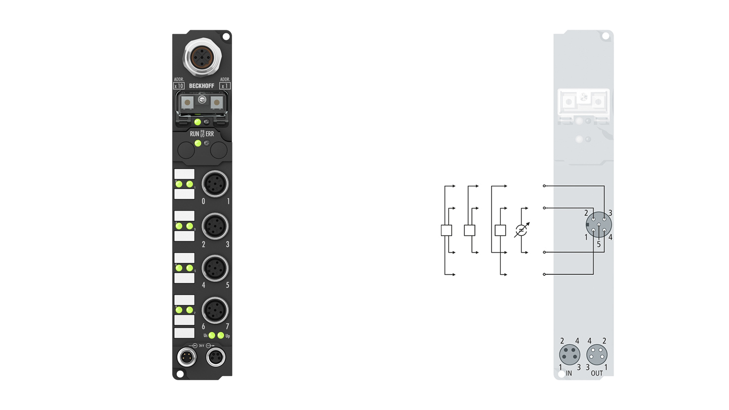
The IP3112 analog input module handles signals in the range from 0/4 to 20 mA. The input current is digitized to a resolution of 16 bits (the default is 15 bits) and is transmitted, electrically isolated, to the higher-level automation device. The four input channels have differential inputs and possess a common, internal ground potential. The applied auxiliary voltage (which can be any value up to 30 V DC) is fed through to supply the sensor. The module is quite versatile, but default settings have been selected in such a way that in most cases it is not necessary to perform configuration. The input filter and associated conversion times can be set within a wide range; several data output formats may be chosen. If required, the inputs can be scaled differently. Automatic limit monitoring is also available. Parameterization may be carried out either via the fieldbus or, using the KS2000 software tool, through the configuration interface. The parameters are stored in the module.
Product status:
service phase | Possibly with other technical features or equipment in case of a service order or repair
Product information
| System data | Modbus | IPxxxx-B730, IL230x-B730 |
|---|---|
| Number of I/O stations | 69 (with repeater) |
| Number of I/O points | depending on controller |
| Data transfer medium | screened, twisted copper cable 2 x 0.25 mm² (RS485) |
| Distance between stations | max. 1200 m (depending on baud rate) |
| Data transfer rates | 150…38,400 baud |
| I/O communication types | read/write access, optionally bit oriented or word oriented |
| Technical data analog inputs | IP3112-Bxxx |
|---|---|
| Number of inputs | 4 |
| Input connections | M12, screw type |
| Signal voltage | 0/4…20 mA |
| Internal resistance | 80 Ω measuring shunt |
| Common-mode voltage UCM | max. 35 V |
| Resolution | 16 bit |
| Measurement error/ uncertainty | < ±0.3 % (relative to full scale value) |
| Conversion time | 250 ms, configurable to 5 ms |
| Nominal voltage | 24 V DC (-15 %/+20 %) |
| Input filter | configurable |
| Sensor supply | from load supply voltage UP |
| Current consumption from US (without sensor current) | see documentation |
| Power supply connection | feed: 1 x M8 male socket, 4-pin; downstream connection: 1 x M8 female socket, 4-pin |
| Bit width in the process image | input: 4 x 16 bit data, optional: 4 x 8 bit control/status |
| Electrical isolation | channels/control voltage: 500 V, between the channels: no, control voltage/fieldbus: depends on the bus system |
| Technical data | IP3112-B730 |
|---|---|
| Extension modules | – |
| Digital peripheral signals | according to I/O type |
| Analog peripheral signals | according to I/O type |
| Protocol | RTU/ASCII |
| Configuration possibility | by means of address selection switch or KS2000 |
| Data transfer rates | 150, 300, 600, 1200, 2400, 4800, 9600, 19,200, 38,400 baud |
| Bus interface | 1 x M12 socket, 5-pin, B-coded |
| Power supply | control voltage: 24 V DC (-15 %/+20 %); load voltage: according to I/O type |
| Power supply connection | feed: 1 x M8 male socket, 4-pin; downstream connection: 1 x M8 female socket, 4-pin |
| Box supply current | 45 mA + current consumption of sensors, max. 0.5 A |
| Auxiliary power current | according to I/O type |
| Electrical isolation | control voltage/fieldbus: yes, control voltage/inputs or outputs: according to I/O type |
| Weight | approx. 210 g |
| Operating/storage temperature | 0…+55 °C/-25…+85 °C |
| Vibration/shock resistance | conforms to EN 60068-2-6/EN 60068-2-27 |
| EMC immunity/emission | conforms to EN 61000-6-2/EN 61000-6-4 |
| Protect. rating/installation pos. | IP65/66/67 (conforms to EN 60529)/variable |
| Approvals/markings | CE, UL |
| Housing data | Standard housing |
|---|---|
| Dimensions (W x H x D) | 30 mm x 175 mm x 26.5 mm |
| Material | PA6 (polyamide) |
| Installation | 2 fixing holes 3.5 mm diameter for M3 |
| Accessories | |
|---|---|
| ZK1020-0101-0xxx | pre-assembled IP-Link cable, drag-chain suitable |
| ZK2000-6100-0xxx | M12, plug, straight, male, 4-pin, A-coded – open end |
| ZK2000-6162-0xxx | M12, plug, straight, male, 4-pin, A-coded – M12, socket, straight, female, 4-pin, A-coded |
| ZK2020-3200-0xxx | M8, socket, straight, female, 4-pin – open end |
| ZK2020-3132-0xxx | M8, plug, straight, male, 4-pin – M8, socket, straight, female, 4-pin |
| ZS1020-0010 | IP-Link plug, 1 piece, plug for IP-Link system |
| ZS2000-2610 | Plug field assembly, Sensor, IP65/67, M12, straight, male, 4-pin, A-coded, 0.14…1.5 mm², Ø 4…8 mm |
| ZS2000-2710 | Plug field assembly, Sensor, IP65/67, M12, straight, male, 5-pin, A-coded, 0.25…1.5 mm², Ø 4…8 mm |
| ZS2000-2310 | Plug field assembly, Sensor and Power, IP65/67, M8, straight, male, 4-pin, A-coded, 0.14…0.5 mm², Ø 4…5.5 mm |
| ZS2000-2320 | Socket field assembly, Sensor and Power, IP65/67, M8, straight, female, 4-pin, A-coded, 0.14…0.5 mm², Ø 4…5.5 mm |
| ZS5300-0011 | Mounting plate for 14 small or 7 wide EtherCAT-/ EtherCAT P box modules, stainless steel, 500 mm x 130 mm x 1.5 mm |
| ZS5000-0014 | blanking plug, plastic (IP65/67), for M8 socket, green, packaging unit = 50 pieces |
| ZS5000-0020 | blanking plug, plastic (IP67), for M12 socket, packaging unit = 50 pieces |
| ZB8801-0000 | torque wrench for hexagonal plugs, adjustable |
| ZB8801-0001 | torque cable key, M8/wrench size 9, for ZB8801-0000 |
| ZB8801-0002 | torque cable key, M12/wrench size 13, for ZB8801-0000 |
Loading content ...
Loading content ...
Loading content ...
© Beckhoff Automation 2024 - Terms of Use


