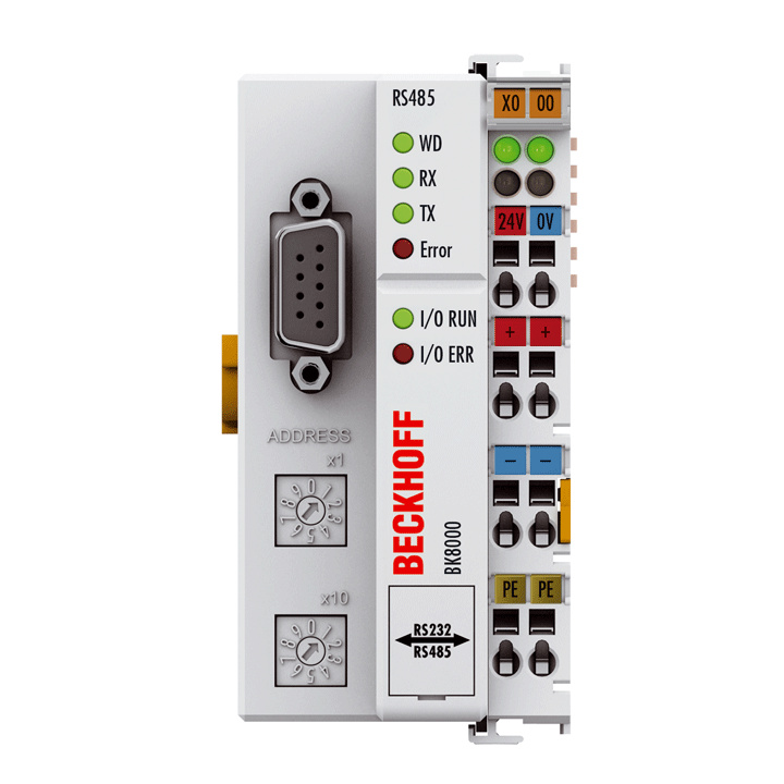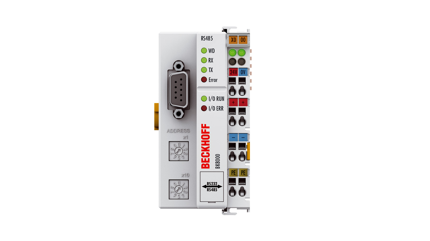
The BK8000 Bus Coupler usess the physics of the RS485 (V.24) specification for data transmission. Application of the Bus Coupler with a serial interface is suited to those cases in which the use of a fieldbus system can be omitted. The RS485 interface can be used by any automation device with the corresponding interface to gain access to the Bus Coupler. Data exchange is made via an open, documented protocol.
Another mode of operation is for the Bus Coupler to function in master/slave mode as a fieldbus multiplexer. The input data from one device are copied directly to the outputs of the other, without the aid of an additional master – and vice versa.
The BK8000 Bus Coupler communicates via an RS485 interface. This permits a bus to be constructed with up to 99 participating devices (addresses can be set with an address selector).
Product status:
regular delivery
Product information
| Technical data | BK8000 |
|---|---|
| Number of Bus Terminals | 64 |
| Max. number of bytes fieldbus | 512 byte input and 512 byte output |
| Digital peripheral signals | 512 inputs/outputs |
| Analog peripheral signals | 256 inputs/outputs |
| Configuration possibility | via KS2000 |
| Protocol | open, documented protocol |
| Data transfer rates | 9.6 kbaud, 19.2 kbaud, 38.4 kbaud |
| Bus interface | RS485 D-sub |
| Data transfer medium | screened, twisted copper cable 2 x 0.25 mm² (RS485) |
| Power supply | 24 V DC (-15%/+20%) |
| Input current | 70 mA + (total K-bus current)/4, 500 mA max. |
| Starting current | 2.5 x continuous current |
| Recommended fuse | ≤ 10 A |
| Current supply K-bus | 1750 mA |
| Power contacts | max. 24 V DC/max. 10 A |
| Electrical isolation | 500 V (power contact/supply voltage/fieldbus) |
| Weight | approx. 170 g |
| Operating temperature | 0…55°C |
| Storage temperature | -25…+85°C |
| Relative humidity | 95%, no condensation |
| Vibration/shock resistance | conforms to EN 60068-2-6/EN 60068-2-27 |
| EMC immunity/emission | conforms to EN 61000-6-2/EN 61000-6-4 |
| Protect. rating/installation pos. | IP20/variable |
| Approvals/markings | CE, CCC, UL, ATEX, IECEx, DNV GL |
| Ex marking | ATEX: II 3 G Ex ec IIC T4 Gc IECEx: Ex ec IIC T4 Gc |
| Housing data | BKxxxx, BCxxxx |
|---|---|
| Design form | compact terminal housing with signal LEDs |
| Material | polycarbonate |
| Dimensions (W x H x D) | 51 mm x 100 mm x 69 mm |
| Installation | on 35 mm DIN rail, conforming to EN 60715 with lock |
| Side by side mounting by means of | double slot and key connection |
| Marking | labeling of the BZxxxx series |
| Wiring | solid conductor (s), flexible conductor (st) and ferrule (f): spring actuation by screwdriver |
| Connection cross-section | s*: 0.08…2.5 mm², st*: 0.08…2.5 mm², f*: 0.14…1.5 mm² |
| Stripping length | 8…9 mm |
| Current load power contacts | Imax: 10 A |
*s: solid wire; st: stranded wire; f: with ferrule
Loading content ...
Loading content ...
Loading content ...
© Beckhoff Automation 2025 - Terms of Use


