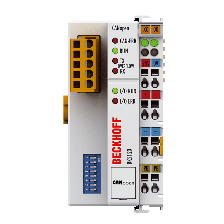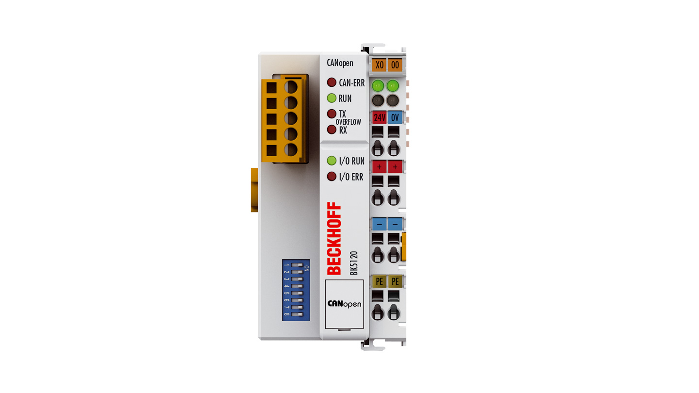
The BK5120 Economy plus Bus Coupler connects the CAN bus system to the electronic terminal blocks, which can be extended in modular fashion. One unit consists of one Bus Coupler, any number of up to 64 terminals and one end terminal. With the K-bus extension technology, the BK5120 allows the connection of up to 255 spatially distributed Bus Terminals to one Bus Coupler.
The Bus Coupler works on the CAN protocol basis as defined in ISO 11898. In addition to network services, CANopen also determines the data allocation for automation systems applications and has established itself as an open CAN application layer. The Bus Coupler supports all types of CANopen communications and can also be used without difficulty in manufacturer-specific CAN environments due to the simple structure of this protocol definition. The firmware can be updated via the configuration interface.
Parameterizing can also be carried out using any CANopen configuration tools. For this, EDS data files are available, which describe all the setting options for the CANopen coupler. For most applications, however, no configuration is necessary, as CANopen provides practical default values for all parameters.
Product status:
regular delivery
Product information
| Technical data | BK5120 |
|---|---|
| Number of Bus Terminals | 64 (255 with K-bus extension) |
| Max. number of bytes fieldbus | 16 Tx/Rx PDOs |
| Digital peripheral signals | 960 inputs/outputs |
| Analog peripheral signals | 60 inputs/outputs |
| Configuration possibility | via KS2000 or the controller |
| Number of PDOs (CANopen) | 16 Tx/16 Rx |
| Additional CANopen features | life, node guarding, emergency object, variable mapping, store/restore |
| Data transfer rates | up to 1 Mbaud |
| Bus interface | 1 x open style connector, 5-pin, included |
| Data transfer medium | screened, twisted copper cable, 2 x signal, 1 x ground (recommended) |
| Power supply | 24 V DC (-15%/+20%) |
| Input current | 70 mA + (total K-bus current)/4, 500 mA max. |
| Starting current | approx. 2.5 x continuous current |
| Recommended fuse | ≤ 10 A |
| Current supply K-bus | 1750 mA |
| Power contacts | max. 24 V DC/max. 10 A |
| Electrical isolation | 500 V (power contact/supply voltage Bus Coupler) |
| PDO modes | synchron, cyclic, event driven, polling |
| Weight | approx. 150 g |
| Operating/storage temperature | -25…+60°C/-40…+85°C |
| Relative humidity | 95%, no condensation |
| Vibration/shock resistance | conforms to EN 60068-2-6/EN 60068-2-27 |
| EMC immunity/emission | conforms to EN 61000-6-2/EN 61000-6-4 |
| Protect. rating/installation pos. | IP20/variable |
| Approvals/markings | CE, UL, ATEX, IECEx, DNV GL |
| Ex marking | ATEX: II 3 G Ex ec IIC T4 Gc IECEx: Ex ec IIC T4 Gc |
| Housing data | BKxxxx, BCxxxx |
|---|---|
| Design form | compact terminal housing with signal LEDs |
| Material | polycarbonate |
| Dimensions (W x H x D) | 51 mm x 100 mm x 69 mm |
| Installation | on 35 mm DIN rail, conforming to EN 60715 with lock |
| Side by side mounting by means of | double slot and key connection |
| Marking | labeling of the BZxxx series |
| Wiring | solid conductor (s), flexible conductor (st) and ferrule (f): spring actuation by screwdriver |
| Connection cross-section | s*: 0.08…2.5 mm², st*: 0.08…2.5 mm², f*: 0.14…1.5 mm² |
| Stripping length | 8…9 mm |
| Current load power contacts | Imax: 10 A |
*s: solid wire; st: stranded wire; f: with ferrule
Loading content ...
Loading content ...
Loading content ...
Loading content ...
© Beckhoff Automation 2024 - Terms of Use


