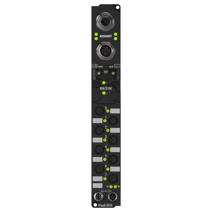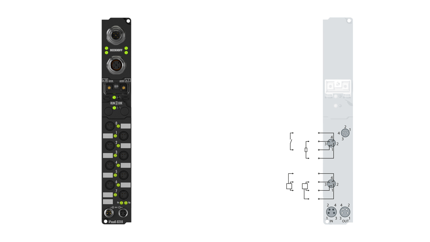
The IP2400-Bxxx digital I/O module has sixteen channels that can be used as eight inputs and eight outputs. The signals are connected through 8 mm snap type connectors, both of which have four pins (with separate input and output pins). Adapter cables are available for use in input-only or output-only cases, as well as connectors for field assemby. It is also possible to use the power supply cable directly as the sensor cable. The outputs handle load currents of up to 0.5 A, are short-circuit proof and protected against inverse polarity. The state of each signal is indicated by means of light emitting diodes.
Product status:
service phase | Possibly with other technical features or equipment in case of a service order or repair. Recommended alternative: IP2401-B310
Product information
| Technical data digital inputs/outputs | IP2400-Bxxx |
|---|---|
| Number of channels | 8 inputs + 8 outputs |
| Input/output connections | 8 mm, snap type |
| Input filter | 3.0 ms |
| “0” signal voltage | -3…+5 V |
| “1” signal voltage | 11…30 V, 6 mA input current (EN 61131-2, type 2) |
| Sensor supply | from control voltage, max. 0.5 A, short-circuit proof in total |
| Load type | ohmic, inductive, lamp load |
| Rated load voltage | 24 V DC (-15%/+20%) |
| Max. output current | 0.5 A per channel, individually short-circuit proof |
| Short-circuit current | typ. 1.5 A |
| Auxiliary power current | typ. 20 mA per channel |
| Current consumption from US (without sensor current) | see documentation |
| Power supply connection | feed: 1 x M8 male socket, 4-pin, a-coded; downstream connection: 1 x M8 female socket, 4-pin, a-coded |
| Bit width in the process image | 8 inputs + 8 outputs |
| Electrical isolation | channels/control voltage: no, between the channels: no, control voltage/fieldbus: depends on the bus system |
| Technical data | IP2400-B310 |
|---|---|
| Configuration possibility | via KS2000 or the controller, DP-V1 extensions are supported |
| Data transfer rates | automatic detection up to 12 Mbaud |
| Bus interface | 1 x M12 socket, 5-pin, B-coded |
| Data transfer medium | shielded copper cable, 2 x 0.25 mm² |
| Power supply | control voltage: 24 V DC (-15%/+20%); load voltage: according to I/O type |
| Power supply connection | feed: 1 x M8 male socket, 4-pin, a-coded; downstream connection: 1 x M8 female socket, 4-pin, a-coded |
| Box supply current | 85 mA + current consumption of sensors, max. 0.5 A |
| Auxiliary power current | according to I/O type |
| Electrical isolation | control voltage/fieldbus: no, control voltage/inputs or outputs: according to I/O type |
| Data transfer time | approx. 0.5 ms with 10 stations each with 32 bit input and output |
| Operating/storage temperature | 0…+55°C/-25…+85°C |
| Vibration/shock resistance | conforms to EN 60068-2-6/EN 60068-2-27 |
| EMC immunity/emission | conforms to EN 61000-6-2/EN 61000-6-4 |
| Protect. rating/installation pos. | IP65/66/67 (conforms to EN 60529)/variable |
| Approvals/markings | CE, UL |
| Housing data | Standard housing |
|---|---|
| Dimensions (W x H x D) | 30 mm x 175 mm x 26.5 mm |
| Material | PA6 (polyamide) |
| Installation | 2 fixing holes 3.5 mm diameter for M3 |
Loading content ...
Loading content ...
Loading content ...
© Beckhoff Automation 2024 - Terms of Use


