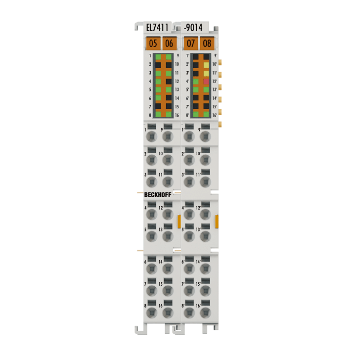
The EL7411-xxxx BLDC motor terminal provides high control performance in a very compact design for the medium output range of BLDC motors. Due to the fast control technology and the connection of an incremental encoder, both very high speed profiles and dynamic positioning tasks can be implemented. Maximum operational reliability is provided through the monitoring of numerous parameters, such as overvoltage, undervoltage, overcurrent, terminal temperature or motor load via the calculation of an I²T model. Moreover, the EL7411-9014 enables the user to implement STO (Safe Torque Off) safety functions corresponding to a Cat. 3, PL d safety level according to DIN EN ISO 13849-1:2015. The terminal's output current can be increased in conjunction with the ZB8610 fan cartridge.
Product status:
product announcement | estimated market release 3rd quarter 2025
Product information
| Technical data | EL7411-9014 |
|---|---|
| Protocol | EtherCAT |
| Technology | compact drive technology |
| Connection method | direct motor connection + feedback |
| Number of inputs | 2 x end position, 1 x encoder, 1 x STO, 1 x fan diag, 3 x Hall effect sensor |
| Load type | BLDC |
| Number of channels | 1 |
| Number of outputs | 1 x BLDC motor, 1 x motor brake, 1 x fan supply, 1 x fan mode, 1 x sensor supply, 1 x encoder supply |
| Supply voltage electronics | 24 V DC (via power contacts) |
| Supply voltage power | 8…48 V DC (external) |
| Output current (rms) | 4.5 A |
| Peak current (rms) | max. 9.0 A for 1 s |
| Performance increase | yes, through ZB8610 fan cartridge |
| Output current with ZB8610 (rms) | 7.0 A up to 55 °C, 8.0 A up to 45 °C operating temperature |
| Peak current with ZB8610 (rms) | max. 16.0 A for 1 s up to 55 °C operating temperature |
| Rotating field frequency | 599 Hz |
| PWM clock frequency | 16 kHz |
| Current controller frequency | 32 kHz |
| Min. motor inductance | 200 µH |
| Output voltage motor brake | 24 V DC |
| Output current motor brake | max. 0.5 A |
| Current consumption power contacts | typ. 50 mA + holding current motor brake |
| Current consumption E-bus | typ. 120 mA |
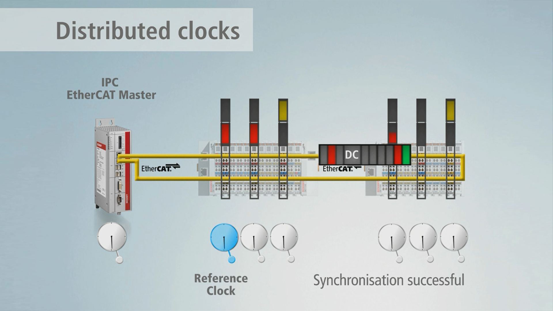
| Distributed clocks | yes |
| Realization STO | hard-wired via safe output |
| Special features | compact and system-integrated, STO |
| Safe stop functions | Safe Torque Off (STO), Safe Stop 1 (SS1) |
| Electrical isolation | 500 V (E-bus/field potential) |
| Weight | approx. 95 g |
| Operating/storage temperature | 0…+55°C/-25…+85°C |
| Relative humidity | 95%, no condensation |
| EMC immunity/emission | conforms to EN 61000-6-2/EN 61000-6-4 |
| Vibration/shock resistance | conforms to EN 60068-2-6/EN 60068-2-27 |
| Protect. rating/installation pos. | IP20/see documentation |
| Approvals/markings | CE, UL |
| Housing data | EL-24-2x16pin |
|---|---|
| Design form | HD (High Density) housing with signal LEDs |
| Material | polycarbonate |
| Dimensions (W x H x D) | 24 mm x 100 mm x 68 mm |
| Installation | on 35 mm DIN rail, conforming to EN 60715 with lock |
| Side by side mounting by means of | double slot and key connection |
| Marking | labeling of the BZxxx series |
| Wiring | solid conductors (s): direct plug-in technique; fine-stranded conductors (st) and ferrule (f): spring actuation by screwdriver |
| Connection cross-section | s*: 0.08…1.5 mm², st*: 0.25…1.5 mm², f*: 0.14…0.75 mm² |
| Connection cross-section AWG | s*: AWG28…16, st*: AWG22…16, f*: AWG26…19 |
| Stripping length | 8…9 mm |
| Current load power contacts | Imax: 10 A |
*s: solid wire; st: stranded wire; f: with ferrule
Loading content ...
Loading content ...
Loading content ...
Loading content ...
© Beckhoff Automation 2024 - Terms of Use


