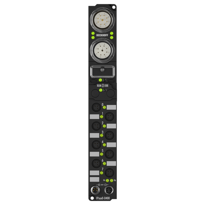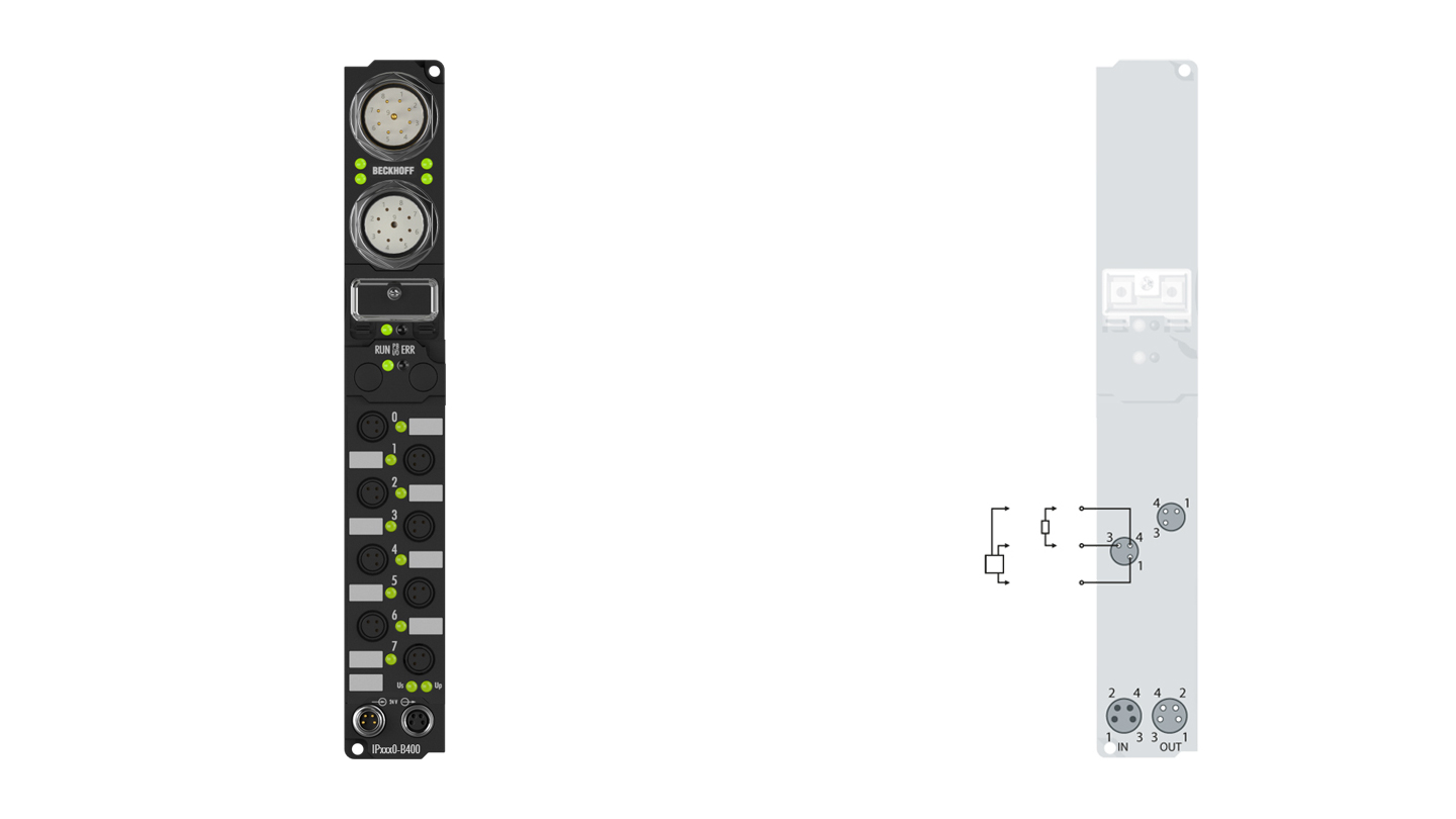
The IP2000-Bxxx digital output connects the binary control signals from the automation unit on to the actuators at the process level. The eight outputs handle load currents of up to 0.5 A and indicate their status through light emitting diodes. The signals are connected via Ø8 mm snap type connectors.
The outputs are short-circuit proof and protected against inverse connection.
Product status:
service phase | Possibly with other technical features or equipment in case of a service order or repair
Product information
| System data | Interbus | IPxxxx-B400, IL230x-B400 |
|---|---|
| Number of I/O stations | depending on the master, max. 256 |
| Number of I/O points | depending on the master |
| Data transfer medium | LiYCY 3 x 2 x 0.22 mm² |
| Cable length | max. 400 m between modules |
| Data transfer rates | 500 kBaud |
| Data transfer time | approx. 1 ms in the case of 10 modules for 32 bit input and output each |
| Technical data digital outputs | IP2000-Bxxx |
|---|---|
| Number of outputs | 8 |
| Output connections | 8 mm, snap type |
| Load type | ohmic, inductive, lamp load |
| Nominal output voltage | 24 V DC (-15 %/+20 %) |
| Max. output current | max. 0.5 A per channel, individually short-circuit proof |
| Short-circuit current | typ. 1.5 A |
| Auxiliary power current | typ. 20 mA per channel |
| Current consumption from US (without sensor current) | see documentation |
| Power supply connection | feed: 1 x M8 male socket, 4-pin; downstream connection: 1 x M8 female socket, 4-pin |
| Bit width in the process image | 8 outputs |
| Electrical isolation | channels/control voltage: no, between the channels: no, control voltage/fieldbus: depends on the bus system |
| Technical data | IP2000-B400 |
|---|---|
| Extension modules | – |
| Digital peripheral signals | according to I/O type |
| Analog peripheral signals | according to I/O type |
| Configuration possibility | via KS2000 |
| Bus interface | 1 x M23 female socket 9-pin, 1 x M23 male socket 9-pin |
| Power supply | control voltage: 24 V DC (20…29 V DC); load voltage: according to I/O type |
| Power supply connection | feed: 1 x M8 male socket, 4-pin; downstream connection: 1 x M8 female socket, 4-pin |
| Box supply current | 85 mA + current consumption of sensors, max. 0.5 A |
| Auxiliary power current | according to I/O type |
| Electrical isolation | control voltage/fieldbus: no, control voltage/inputs or outputs: according to I/O type |
| Weight | approx. 350 g |
| Operating/storage temperature | 0…+55 °C/-25…+85 °C |
| Vibration/shock resistance | conforms to EN 60068-2-6/EN 60068-2-27 |
| EMC immunity/emission | conforms to EN 61000-6-2/EN 61000-6-4 |
| Protect. rating/installation pos. | IP65/66/67 (conforms to EN 60529)/variable |
| Housing data | XXL housing |
|---|---|
| Dimensions (W x H x D) | 30 mm x 210 mm x 26.5 mm |
| Material | PA6 (polyamide) |
| Installation | 2 fixing holes 3.5 mm diameter for M3 |
Loading content ...
Loading content ...
© Beckhoff Automation 2024 - Terms of Use


