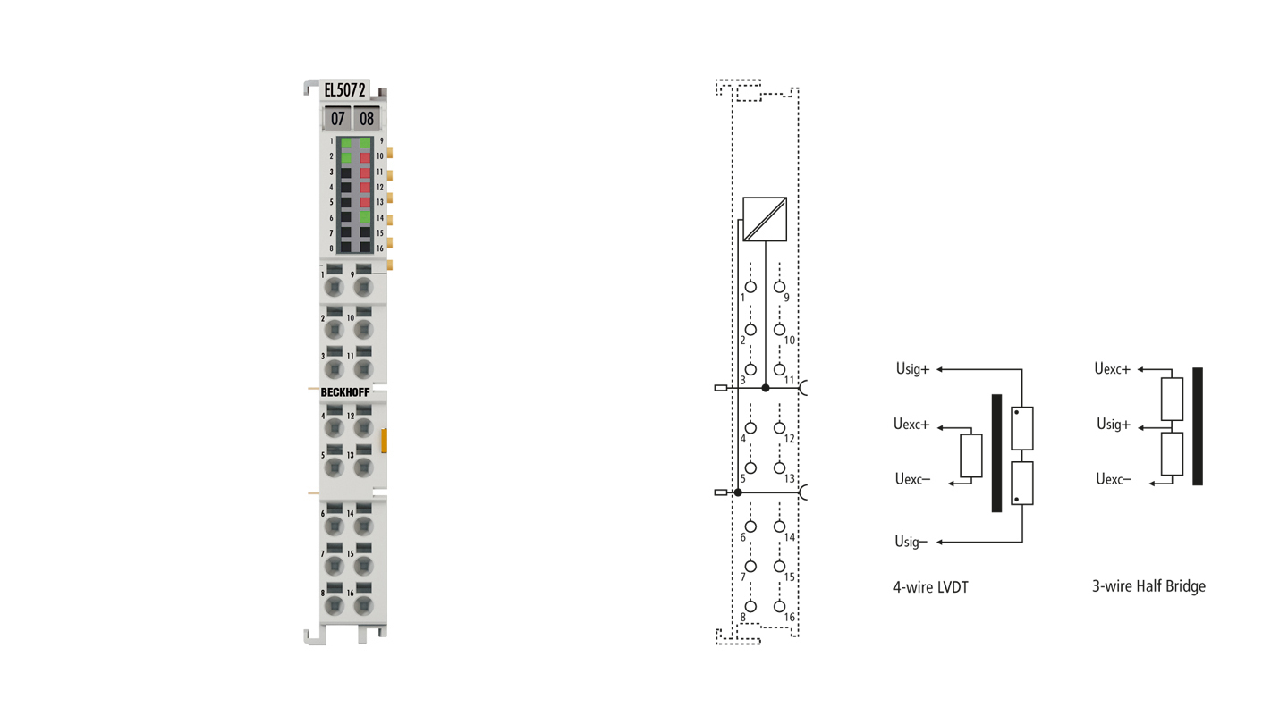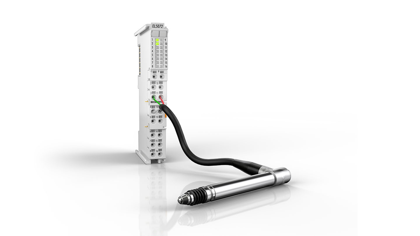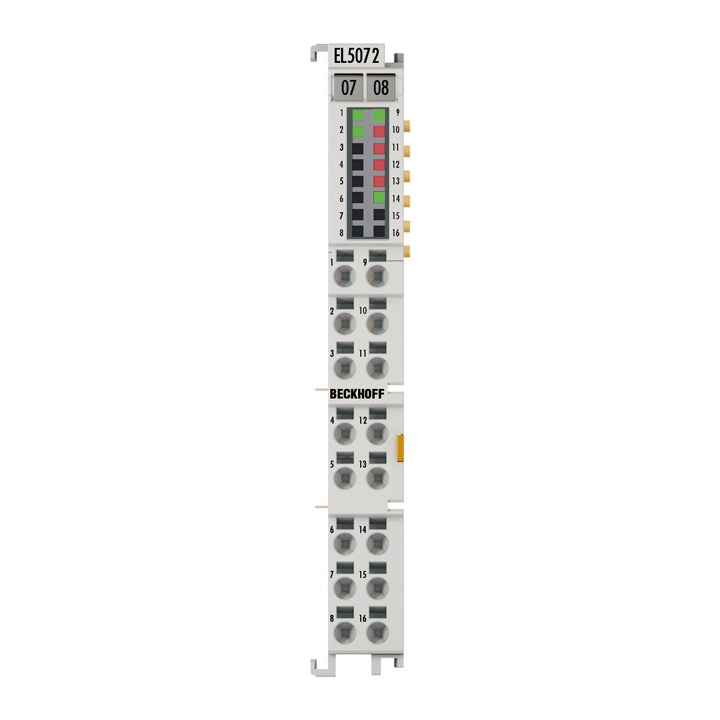
The EL5072 EtherCAT Terminal is used for the direct connection of up to two inductive displacement sensors, which include measuring probes in LVDT and half bridge versions or inductive angle position sensors in RVDT version. The integrated excitation source provides a further area with various excitation frequencies and voltages. By internal switching and switchable input impedances, commercially available inductive sensors such as LVDT in 4-, 5-, 6-wire technology to half-bridge in 3- and 5-wire technology can be connected and evaluated.
Special features:
- evaluation of inductive measuring probes in LVDT, RVDT and half-bridge versions
- integrated excitation source with parameterizable frequencies and voltages
- switchable input impedances
- output of the measured value as a position value
- digital input for setting and saving the position value
All sensor parameters such as excitation frequency, excitation voltage, measuring range and sensitivity are set directly in the terminal. The measuring signal range is automatically adjusted; the measured value is directly output as a 32-bit position value. Inversion of the measuring signal and a reference position can be parameterized via the process data. Furthermore, short circuit and overload of the excitation source as well as amplitude errors of the measuring signal are diagnosed per channel and displayed by signal LEDs. One digital input is available per channel for setting and saving the current position value; a timestamp can be generated for the stored value.
Precision measuring tasks in the area of position and distance measurement with inductive measuring probes can be successfully solved in this way with the EL5072.
Product status:
regular delivery
Product information
| Technical data | EL5072 |
|---|---|
| Technology | inductive sensor interface |
| Input connections | LVDT (ratiometric & differential), inductive half bridge, RVDT |
| Number of channels | 2 |
| Distributed clocks | yes, save timestamp for position value via digital input |
| Excitation voltage Uexc | 0.5 Vrms to 7 Vrms (1.5 VPP to 20 VPP), joint source for both channels |
| Total excitation current | max. 50 mArms (140 mAPP) |
| Excitation frequency (sinus) | 1 kHz up to 20 kHz, adjustable |
| Resolution | 24 bit, 32 bit presentation |
| Measuring signal range USIG | max. 7 Vrms (automatic adjustment) |
| Conversion time | 100 µs/10 ksps at max. 13 kHz |
| Current consumption power contacts | typ. 40 mA + load |
| Current consumption E-bus | typ. 200 mA |
| Electrical isolation | 500 V (E-bus/field potential) |
| Special features | short circuit, overload and amplitude error detection per channel, digital input for setting and storing position value |
| Weight | approx. 60 g |
| Operating temperature | 0…55°C |
| Storage temperature | -25…+85°C |
| Relative humidity | 95%, no condensation |
| Vibration/shock resistance | conforms to EN 60068-2-6/EN 60068-2-27 |
| EMC immunity/emission | conforms to EN 61000-6-2/EN 61000-6-4 |
| Protect. rating/installation pos. | IP20/variable |
| Approvals/markings | CE, UL |
| Housing data | EL-12-16pin |
|---|---|
| Design form | HD (High Density) housing with signal LEDs |
| Material | polycarbonate |
| Dimensions (W x H x D) | 12 mm x 100 mm x 68 mm |
| Installation | on 35 mm DIN rail, conforming to EN 60715 with lock |
| Side by side mounting by means of | double slot and key connection |
| Marking | labeling of the BZxxx series |
| Wiring | solid conductors (s): direct plug-in technique; fine-stranded conductors (st) and ferrule (f): spring actuation by screwdriver |
| Connection cross-section | s*: 0.08…1.5 mm², st*: 0.25…1.5 mm², f*: 0.14…0.75 mm² |
| Connection cross-section AWG | s*: AWG28…16, st*: AWG22…16, f*: AWG26…19 |
| Stripping length | 8…9 mm |
| Current load power contacts | Imax: 10 A |
*s: solid wire; st: stranded wire; f: with ferrule
Loading content ...
Loading content ...
Loading content ...
Loading content ...
© Beckhoff Automation 2025 - Terms of Use
