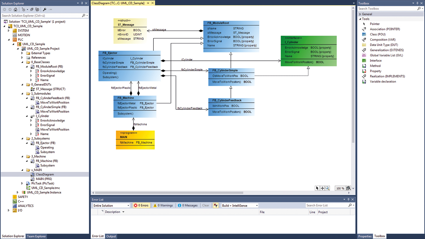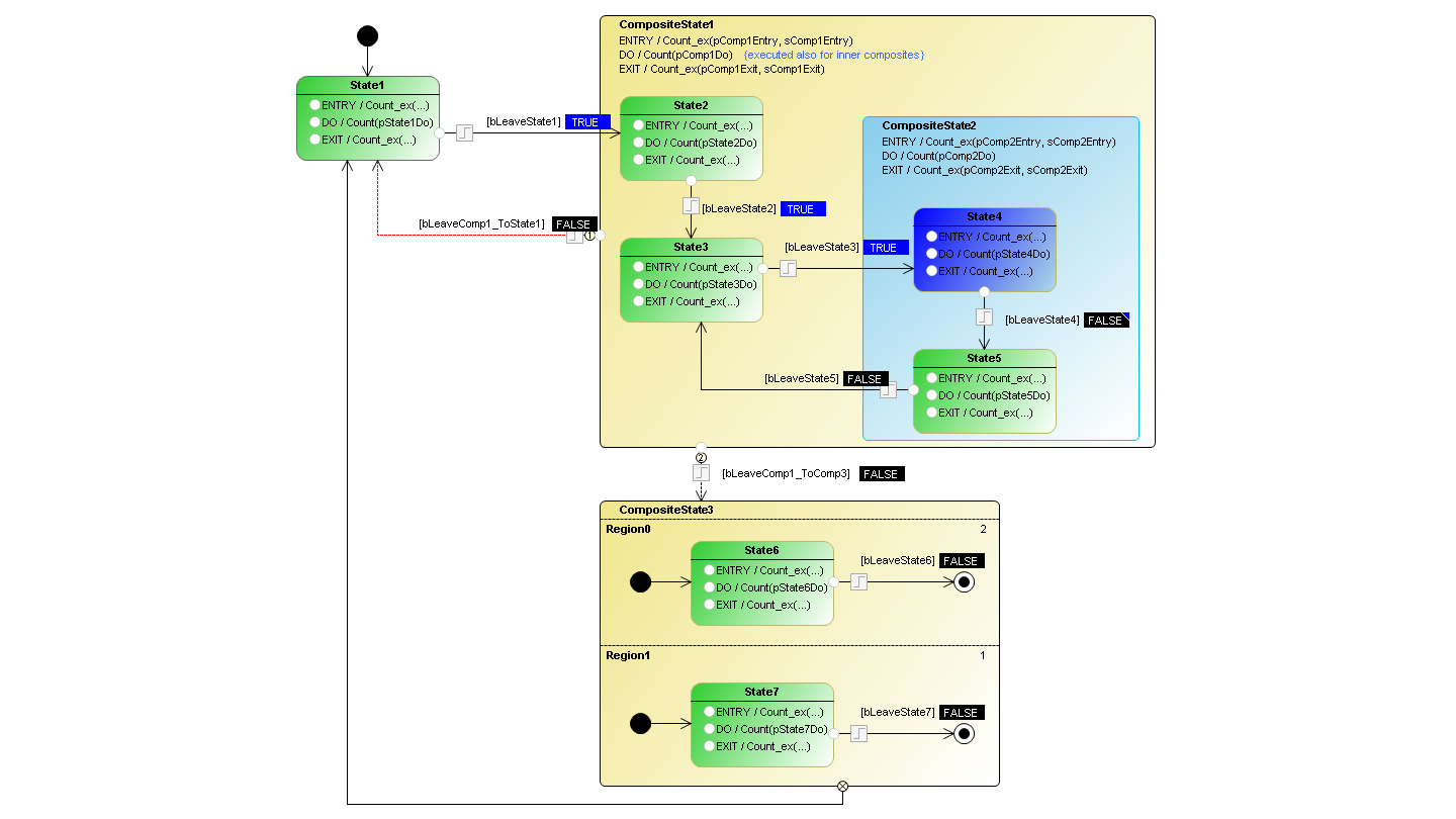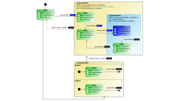
With the integration of UML (Unified Modeling Language) in TwinCAT 3.1, two additional editors for modeling of PLC software are available. The existing TwinCAT PLC programming languages are extended with the UML class and UML state diagrams.
UML in general
UML is a graphical language for software analysis, design and documentation. UML is particularly suitable for object-oriented implementations. The unified modeling of the PLC application results in easy to follow software documentation, which lends itself to analysis and discussion by non-programming specialists.
UML diagrams in TwinCAT 3.1 PLC
The UML class diagram belongs to the group of UML structure diagrams and can be used for schematic representation of the software architecture: Object classes, elements contained within them and object relationships can be represented in a transparent manner. The UML state diagram is part of the UML behavior diagrams and is used for dynamic software modeling. It can be used for a graphic specification of the dynamic response or the state-dependent system behavior. Compilation of the state diagram generates program code, so that the state machine can be executed directly. The development process is supported by an online debugging option.
Function
UML diagrams provide a graphical representation that does not focus on technical details. They therefore provide a good overview of the PLC project. This allows, for example, software requirements to be checked before full implementation, which prevents incomplete or incorrect application implementation. The graphical representation of the control code in a UML diagram also facilitates the development of a well-thought-out software architecture. Such an architecture forms the basis for the simple and goal-oriented implementation of even complex systems/requirements. Such a software architecture can help to develop self-sufficient modules that can be reused in a time- and cost-saving manner. In general, a well-planned software leads as a rule to fewer programming errors and thus to a higher code quality. Graphical access to the software also facilitates maintenance and debugging. Last but not least, UML diagrams can be used to create generally understandable software documentation. On the one hand this can be used as a coordination tool in the development team, for example to exchange ideas and concepts or to define requirements. On the other hand UML diagrams can help to make the control application accessible to non-programming specialists such as mechanical engineers or process engineers.
Download note: Please license only, it is included in the installation of TwinCAT 3.1 - eXtended Automation Engineering (XAE).
Product status:
regular delivery
Product information
| Technical data | TF1910 |
|---|---|
| Required license | TC1200 |
| Operating system | Windows 7, Windows 10, Windows CE, TwinCAT/BSD |
| CPU architecture | x86, x64, Arm® |

| Ordering information | |
|---|---|
| TF1910-0v20 | TwinCAT 3 UML, platform level 20 (Economy) |
| TF1910-0v30 | TwinCAT 3 UML, platform level 30 (Economy Plus) |
| TF1910-0v40 | TwinCAT 3 UML, platform level 40 (Performance) |
| TF1910-0v50 | TwinCAT 3 UML, platform level 50 (Performance Plus) |
| TF1910-0v60 | TwinCAT 3 UML, platform level 60 (Mid Performance) |
| TF1910-0v70 | TwinCAT 3 UML, platform level 70 (High Performance) |
| TF1910-0v80 | TwinCAT 3 UML, platform level 80 (Very High Performance) |
| TF1910-0v81 | TwinCAT 3 UML, platform level 81 (Very High Performance) |
| TF1910-0v82 | TwinCAT 3 UML, platform level 82 (Very High Performance) |
| TF1910-0v83 | TwinCAT 3 UML, platform level 83 (Very High Performance) |
| TF1910-0v84 | TwinCAT 3 UML, platform level 84 (Very High Performance) |
| TF1910-0v90 | TwinCAT 3 UML, platform level 90 (Other) |
| TF1910-0v91 | TwinCAT 3 UML, platform level 91 (Other 5…8 Cores) |
| TF1910-0v92 | TwinCAT 3 UML, platform level 92 (Other 9…16 Cores) |
| TF1910-0v93 | TwinCAT 3 UML, platform level 93 (Other 17…32 Cores) |
| TF1910-0v94 | TwinCAT 3 UML, platform level 94 (Other 33…64 Cores) |
We recommend using a TwinCAT 3 license dongle for platform levels 90-94.
Loading content ...
Loading content ...
Loading content ...
© Beckhoff Automation 2024 - Terms of Use

