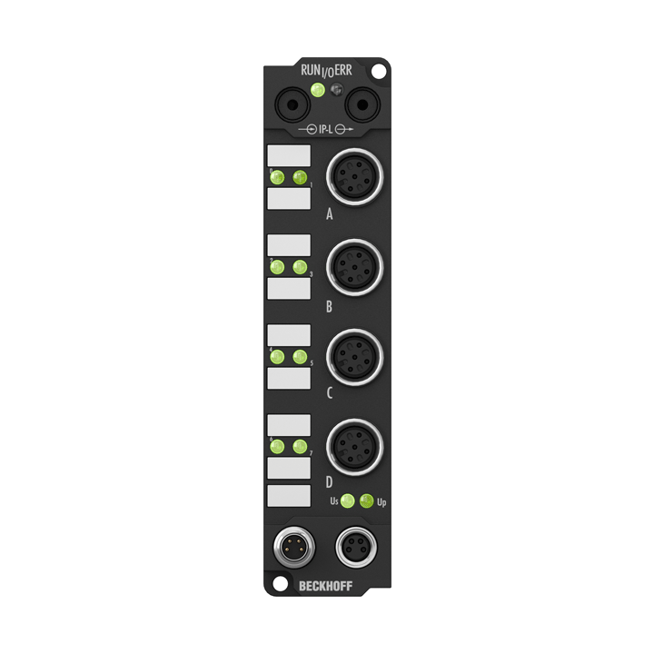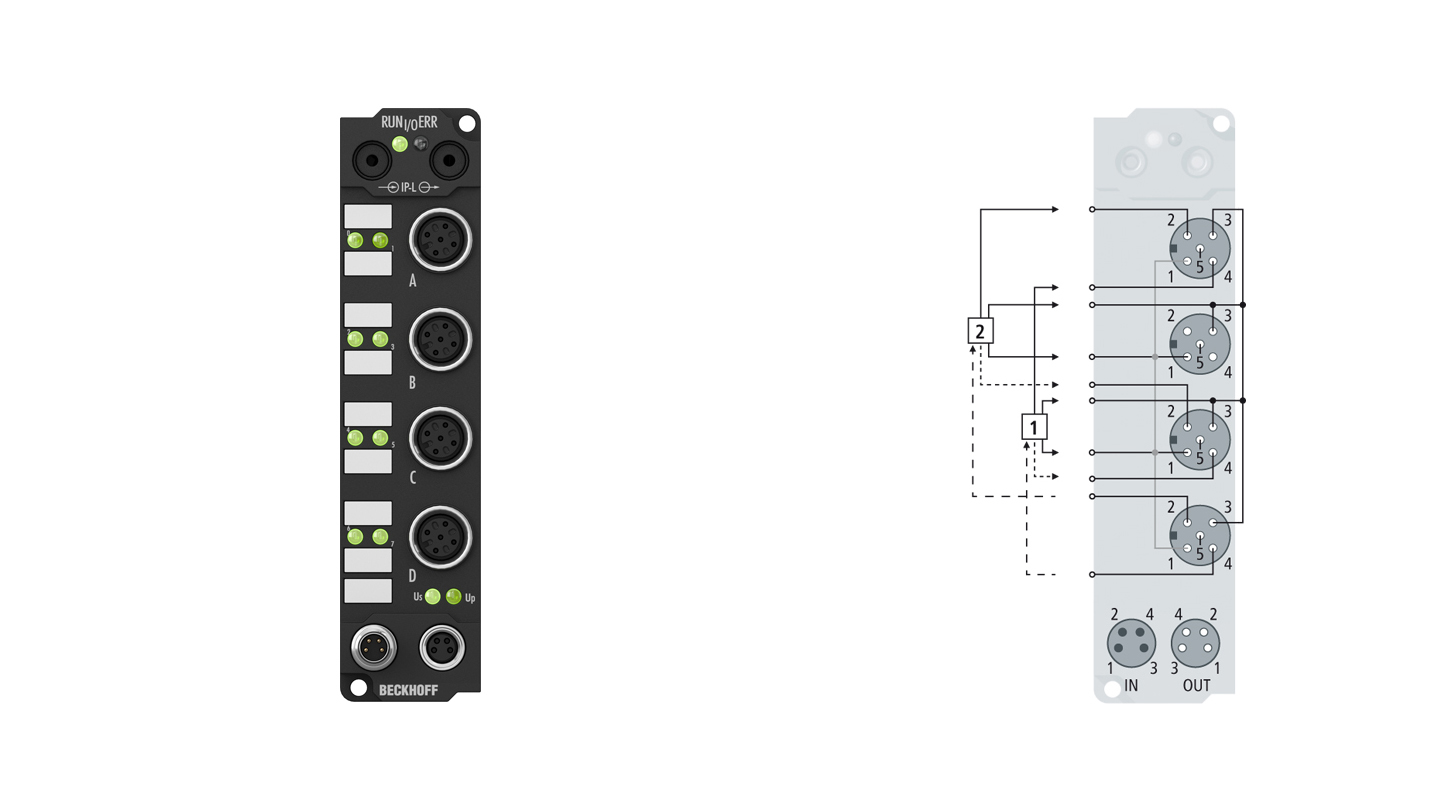
The counter module has two fast counters running at up to 100 kHz. It counts binary pulses and transmits the counter state to the higher-level automation unit. The up/down input allows the counters to be switched between upwards and downwards counting (in 32 bits). The gate signals (gate inputs) allow the counters to be triggered: Depending on the level at the gate input, the counting function is halted or enabled. The outputs can be switched according to the counter state, and can therefore be used as fast control signals for field devices. From the controller it is possible to set the counter state, to start or halt the counter function, and to set the outputs. The signal state of the inputs and outputs is indicated by light emitting diodes.
Product status:
regular delivery
Product information
| Technical data | IE1502 |
|---|---|
| Number of inputs | 2 counter inputs + 2 gate inputs + 2 up/down switches |
| Input connections | M12, screw type |
| Number of counters | 2, each with a depth of 32 bits |
| Counting frequency | 100 kHz (2 kHz for switching between up and down) |
| Nominal input voltage | 24 V DC (-15%/+20%) |
| “0” signal voltage | -3…+5 V (EN 61131-2, type 2) |
| “1” signal voltage | 11…30 V (EN 61131-2, type 2) |
| Number of outputs | 2 x 24 V DC, 0.5 A, individually short-circuit-proof |
| Sensor supply | from control voltage, max. 0.5 A, short-circuit proof in total |
| Power supply connection | feed: 1 x M8 male socket, 4-pin, a-coded; downstream connection: 1 x M8 female socket, 4-pin, a-coded |
| Bit width in the process image | 80 inputs/outputs: 2 x 32 bit data (2 x 8 bit control/status) |
| Current consumption from US (without sensor current) | 25 mA |
| Electrical isolation | channels/control voltage: no, between the channels: no, control voltage/fieldbus: yes, via IP-Link |
| Operating/storage temperature | 0…+55°C/-25…+85°C |
| Vibration/shock resistance | conforms to EN 60068-2-6/EN 60068-2-27 |
| EMC immunity/emission | conforms to EN 61000-6-2/EN 61000-6-4 |
| Protect. rating/installation pos. | IP65/66/67 (conforms to EN 60529)/variable |
| Approvals/markings | CE, UL |
| Housing data | Extension Box |
|---|---|
| Dimensions (W x H x D) | 30 mm x 126 mm x 26.5 mm |
| Material | PA6 (polyamide) |
| Installation | 2 fixing holes 3.5 mm diameter for M3 |
Loading content ...
Loading content ...
Loading content ...
© Beckhoff Automation 2024 - Terms of Use


