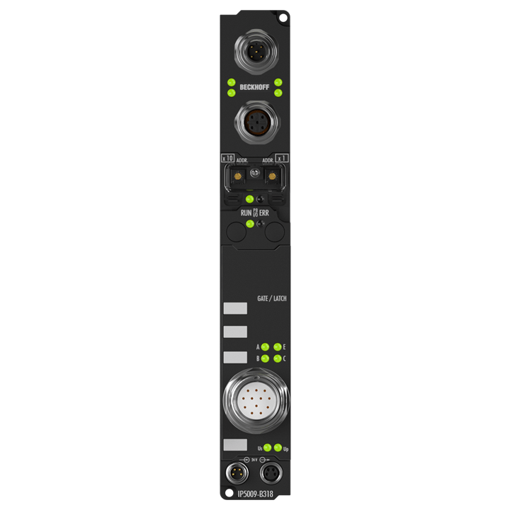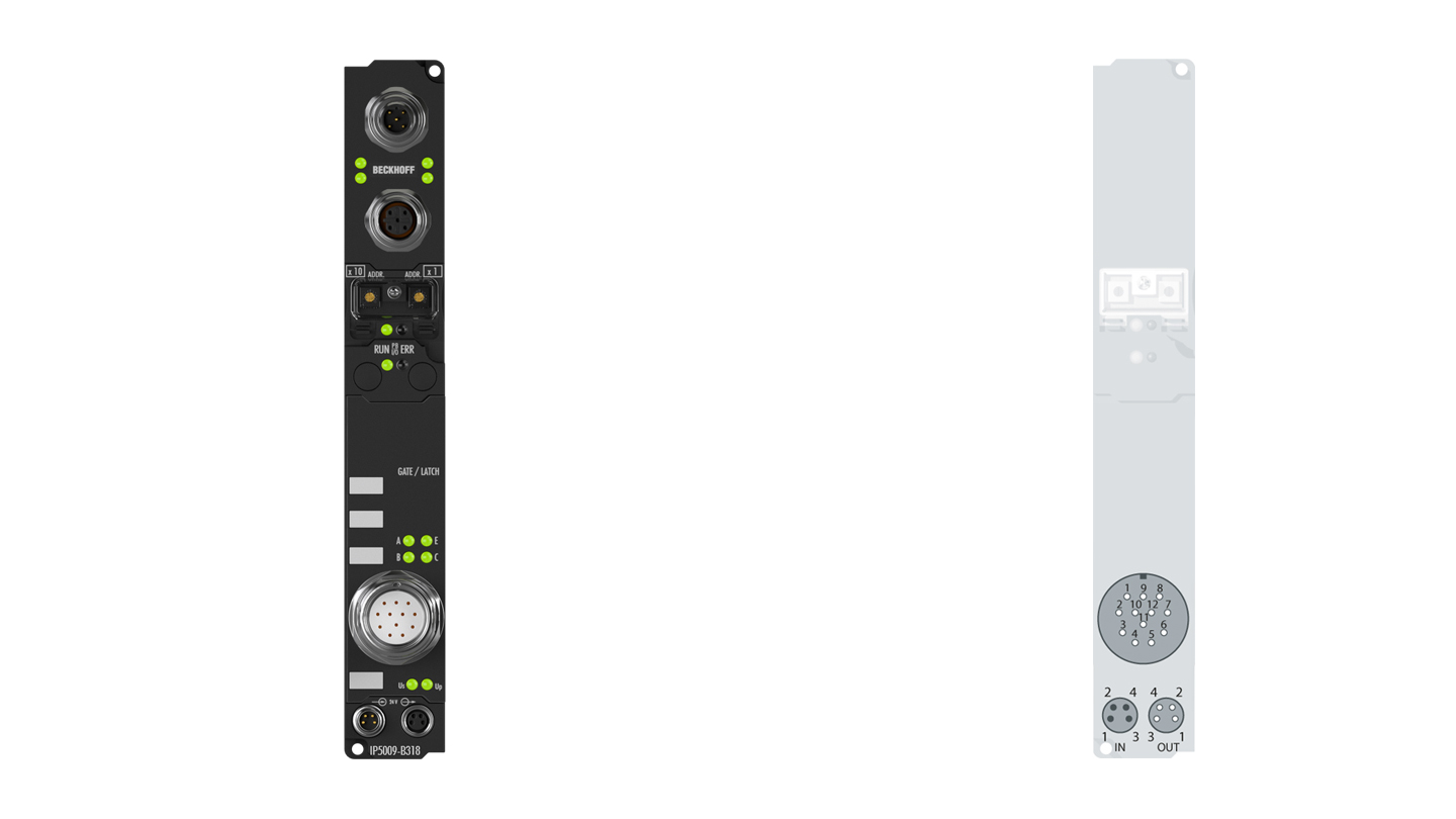
The IP5009 SSI interface module allows an SSI encoder to be connected directly. The encoder is powered via the SSI interface. The interface circuit generates a pulse for reading the encoder and makes the incoming data stream available to the controller as a data word in the process image. The module can optionally provide the data as binary numbers or as a binary gray code. Various operating modes, transmission frequencies and bit widths can be permanently stored in a control register.
Product status:
regular delivery
Product information
| Technical data position measurement | IP5009-Bxxx |
|---|---|
| Connection technology | M23 connector with outer thread, 12-pin |
| Number of channels | 1 |
| SSI encoder connection | M23 connector with outer thread, 12-pin |
| Nominal voltage | 24 V DC (-15%/+20%) |
| Signal input | difference signal (RS485) |
| Encoder supply | 24 V DC, from load voltage |
| Sensor supply | from control voltage, max. 0.5 A, short-circuit proof in total |
| Data transfer rates | variable up to 1 MHz, 250 kHz default |
| Serial input | 24 bits (adjustable) |
| Data direction | read |
| Power supply connection | feed: 1 x M8 male socket, 4-pin, a-coded; downstream connection: 1 x M8 female socket, 4-pin, a-coded |
| Current consumption from US (without sensor current) | see documentation |
| Bit width in the process image | input: 1 x 32 bit data (1 x 8 bit control/status optional) |
| Electrical isolation | depends on the bus system |
| Technical data | IP5009-B318 |
|---|---|
| Configuration possibility | via KS2000 or the controller, DP-V1 extensions are supported |
| Data transfer rates | automatic detection up to 12 Mbaud |
| Bus interface | 1 x M12 socket, 5-pin, 1 x M12 plug, 5-pin (tee-connector integrated), B-coded |
| Data transfer medium | shielded copper cable, 2 x 0.25 mm² |
| Power supply | control voltage: 24 V DC (-15%/+20%); load voltage: according to I/O type |
| Power supply connection | feed: 1 x M8 male socket, 4-pin, a-coded; downstream connection: 1 x M8 female socket, 4-pin, a-coded |
| Box supply current | 85 mA + current consumption of sensors, max. 0.5 A |
| Auxiliary power current | according to I/O type |
| Electrical isolation | control voltage/fieldbus: no, control voltage/inputs or outputs: according to I/O type |
| Data transfer time | approx. 0.5 ms with 10 stations each with 32 bit input and output |
| Operating temperature | 0…55°C |
| Storage temperature | -25…+85°C |
| Vibration/shock resistance | conforms to EN 60068-2-6/EN 60068-2-27 |
| EMC immunity/emission | conforms to EN 61000-6-2/EN 61000-6-4 |
| Protect. rating/installation pos. | IP65/66/67 (conforms to EN 60529)/variable |
| Approvals/markings | CE, UL |
| Housing data | XXL housing |
|---|---|
| Dimensions (W x H x D) | 30 mm x 210 mm x 26.5 mm |
| Material | PA6 (polyamide) |
| Installation | 2 fixing holes 3.5 mm diameter for M3 |
| Accessories | |
|---|---|
| ZS5300-0003 | Mounting plate for Coupler Box, zinc-coated steel sheet, 270 mm x 30 mm x 1.5 mm |
Loading content ...
Loading content ...
© Beckhoff Automation 2025 - Terms of Use


