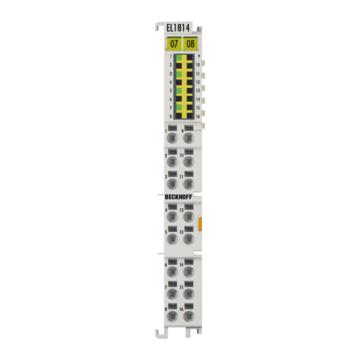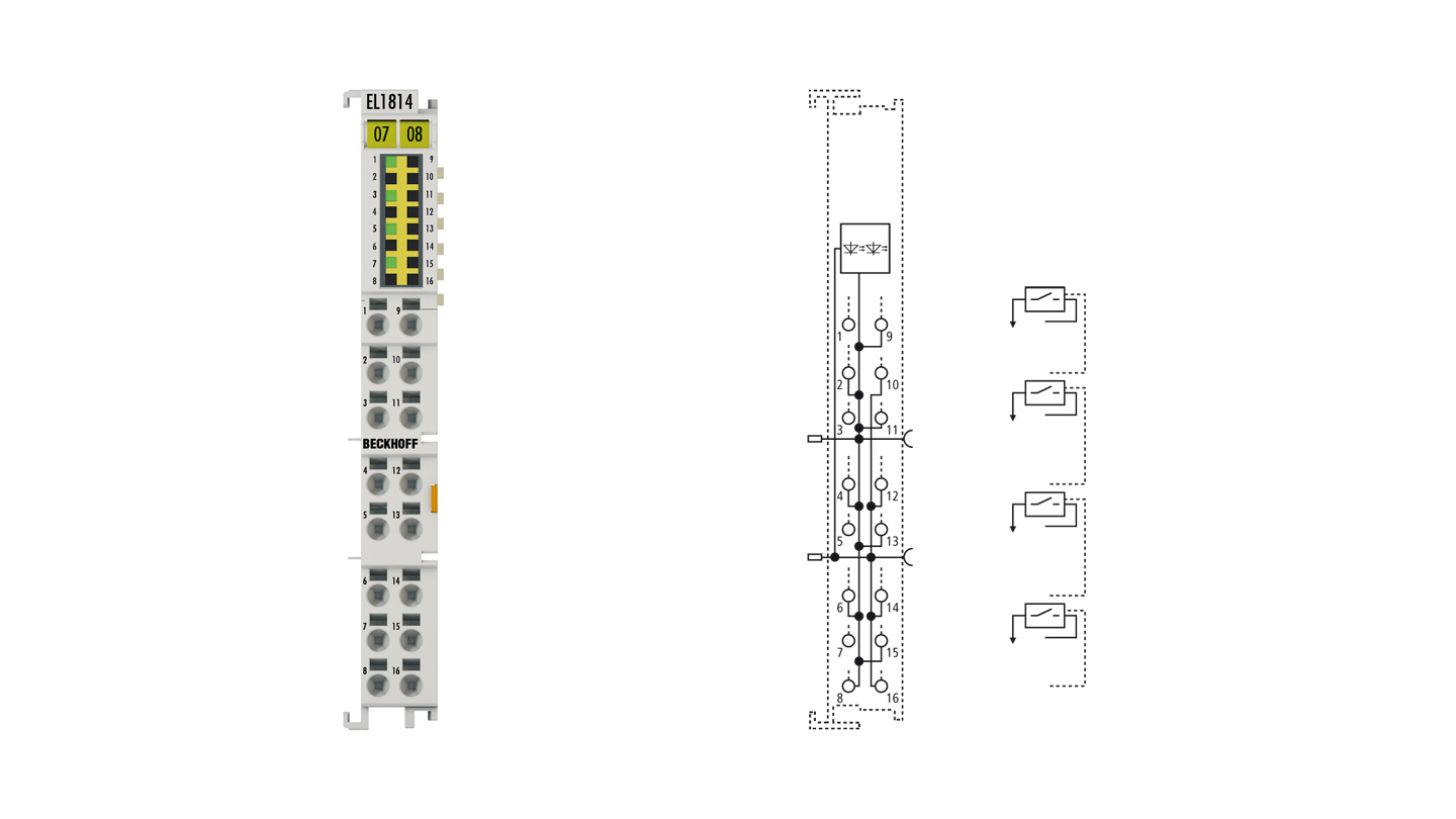
The EL1814 digital input terminal acquires the binary 24 V control signals from the process level and transmits them, in an electrically isolated form, to the higher-level automation unit. The EtherCAT Terminal contains four channels whose signal state is indicated by LEDs. The power contacts are connected through. With the EL1814, the reference ground for all inputs is the 0 V power contact.
Special features:
- input specification type 1/3
- low delay due to fast 10 µs input filter
- usable, for example, for inductive or capacitive sensors
- +24 V and 0 V sensor supply connections
- tool-free connection by direct plug-in technique for solid wire conductors
- increased packing density with 16 connection points in the housing of a 12 mm terminal block
Product status:
regular delivery
Product information
| Technical data | EL1814 |
|---|---|
| Connection technology | 3-wire |
| Specification | EN 61131-2, type 1/3 |
| Number of inputs | 4 |
| Nominal voltage | 24 V DC (-15%/+20%) |
| “0” signal voltage | -3…+5 V (EN 61131-2, type 1/3) |
| “1” signal voltage | 11…30 V (EN 61131-2, type 3) |
| Input current | typ. 3 mA (EN 61131-2, type 3) |
| Input filter | typ. 10 µs |
| Distributed clocks | – |
| Current consumption power contacts | typ. 2 mA + load |
| Current consumption E-bus | typ. 90 mA |
| Electrical isolation | 500 V (E-bus/field potential) |
| Configuration | no address or configuration setting |
| Weight | approx. 60 g |
| Operating temperature | -25…+60°C |
| Storage temperature | -40…+85°C |
| Relative humidity | 95%, no condensation |
| Vibration/shock resistance | conforms to EN 60068-2-6/EN 60068-2-27 |
| EMC immunity/emission | conforms to EN 61000-6-2/EN 61000-6-4 |
| Protect. rating/installation pos. | IP20/variable (see documentation) |
| Approvals/markings | CE, CCC, UL, ATEX, IECEx |
| Ex marking | ATEX: II 3 G Ex ec IIC T4 Gc IECEx: Ex ec IIC T4 Gc |
| Housing data | EL-12-16pin |
|---|---|
| Design form | HD (High Density) housing with signal LEDs |
| Material | polycarbonate |
| Dimensions (W x H x D) | 12 mm x 100 mm x 68 mm |
| Installation | on 35 mm DIN rail, conforming to EN 60715 with lock |
| Side by side mounting by means of | double slot and key connection |
| Marking | labeling of the BZxxx series |
| Wiring | solid conductors (s): direct plug-in technique; fine-stranded conductors (st) and ferrule (f): spring actuation by screwdriver |
| Connection cross-section | s*: 0.08…1.5 mm², st*: 0.25…1.5 mm², f*: 0.14…0.75 mm² |
| Connection cross-section AWG | s*: AWG28…16, st*: AWG22…16, f*: AWG26…19 |
| Stripping length | 8…9 mm |
| Current load power contacts | Imax: 10 A |
*s: solid wire; st: stranded wire; f: with ferrule
Loading content ...
Loading content ...
Loading content ...
Loading content ...
© Beckhoff Automation 2025 - Terms of Use


