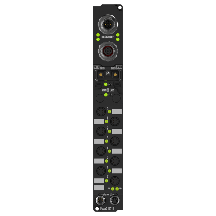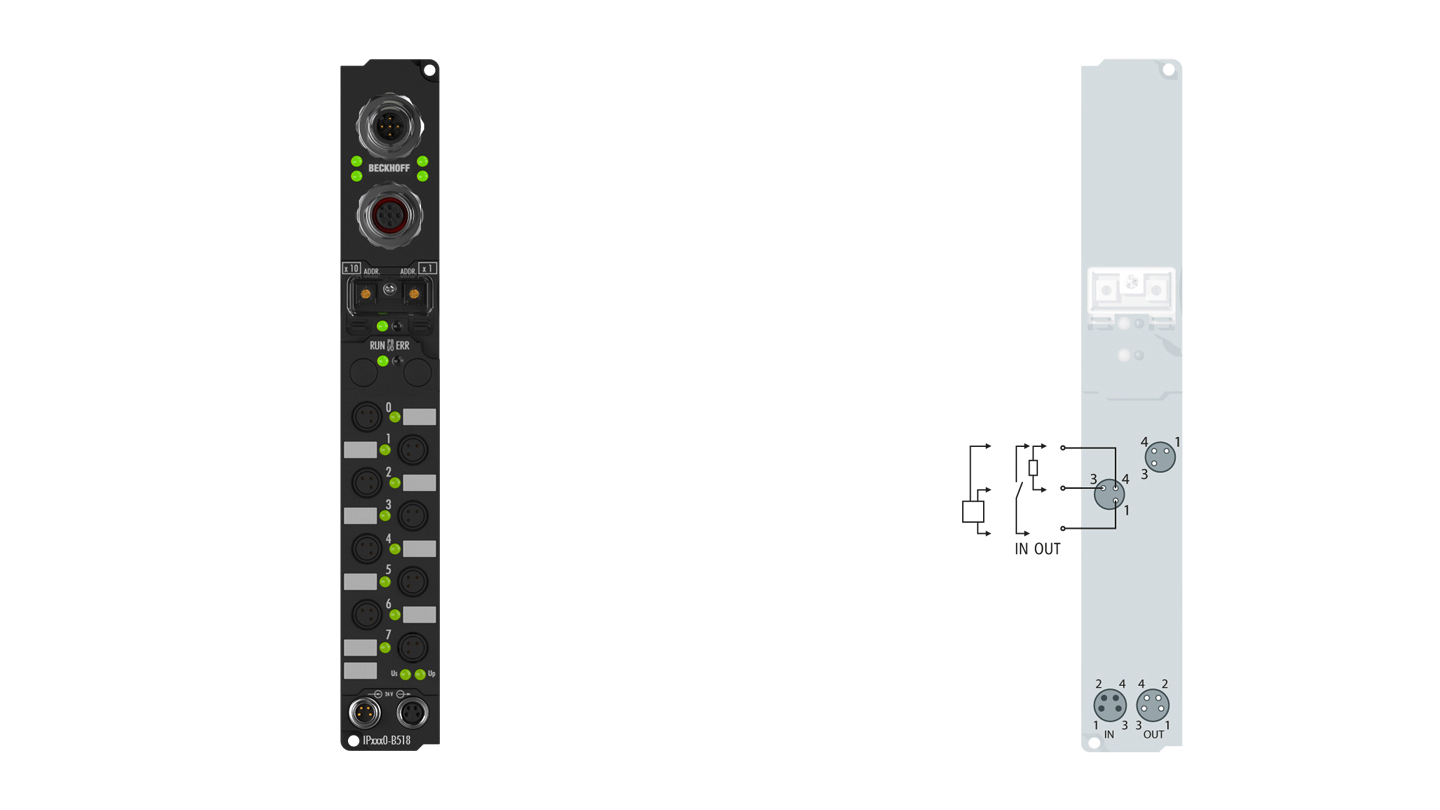
The IP2330-Bxxx digital I/O module combines four digital inputs and four digital outputs in one device. The outputs handle load currents of up to 2 A, are short-circuit-proof and protected against inverse polarity. The total current for all four outputs is limited to 4 A. This makes these modules particularly suitable for applications in which not all of the outputs are active at the same time or in which not all of the actuators draw 2 A signal current. The state of each signal is indicated by means of light emitting diodes. The signals are connected via 8 mm snap type connectors.
Product status:
service phase | Possibly with other technical features or equipment in case of a service order or repair. Recommended alternative: IP2331-B518
Product information
| Technical data digital inputs/outputs | IP2330-Bxxx |
|---|---|
| Number of channels | 4 inputs + 4 outputs |
| Input/output connections | 8 mm, snap type |
| Input filter | 0.2 ms |
| “0” signal voltage | -3…+5 V |
| “1” signal voltage | 11…30 V, 6 mA input current (EN 61131-2, type 2) |
| Sensor supply | from control voltage, max. 0.5 A, short-circuit proof in total |
| Load type | ohmic, inductive, lamp load |
| Rated load voltage | 24 V DC (-15%/+20%) |
| Max. output current | 2 A per channel, individually short-circuit proof, ∑ 4 A |
| Short-circuit current | typ. 4 A |
| Auxiliary power current | typ. 30 mA per channel |
| Current consumption from US (without sensor current) | see documentation |
| Power supply connection | feed: 1 x M8 male socket, 4-pin, a-coded; downstream connection: 1 x M8 female socket, 4-pin, a-coded |
| Bit width in the process image | 4 inputs + 4 outputs |
| Electrical isolation | channels/control voltage: no, between the channels: no, control voltage/fieldbus: depends on the bus system |
| Technical data | IP2330-B518 |
|---|---|
| Extension modules | – |
| Digital peripheral signals | according to I/O type |
| Analog peripheral signals | according to I/O type |
| Number of PDOs (CANopen) | 16 send and 16 receive process data objects |
| Additional CANopen features | life, node guarding, emergency object, variable mapping, store/restore |
| Configuration possibility | through KS2000 or the controller (service data objects) |
| Data transfer rates | automatic detection of 10 kbaud up to 1 Mbaud |
| Bus interface | 1 x M12 plug, 5-pin, 1 x M12 socket, 5-pin (tee-connector integrated) |
| Data transfer medium | shielded copper cable, 2 x signal, 1 x CAN ground (recommended) |
| Power supply | control voltage: 24 V DC (-15%/+20%); load voltage: according to I/O type |
| Power supply connection | feed: 1 x M8 male socket, 4-pin, a-coded; downstream connection: 1 x M8 female socket, 4-pin, a-coded |
| Box supply current | 45 mA + current consumption of sensors, max. 0.5 A |
| Auxiliary power current | according to I/O type |
| Electrical isolation | control voltage/fieldbus: 500 V, control voltage/inputs or outputs: according to I/O type |
| I/O communication types | event driven, cyclic, synchron, polling |
| Operating/storage temperature | 0…+55°C/-25…+85°C |
| Vibration/shock resistance | conforms to EN 60068-2-6/EN 60068-2-27 |
| EMC immunity/emission | conforms to EN 61000-6-2/EN 61000-6-4 |
| Protect. rating/installation pos. | IP65/66/67 (conforms to EN 60529)/variable |
| Approvals/markings | CE, UL |
| Housing data | XXL housing |
|---|---|
| Dimensions (W x H x D) | 30 mm x 210 mm x 26.5 mm |
| Material | PA6 (polyamide) |
| Installation | 2 fixing holes 3.5 mm diameter for M3 |
Loading content ...
Loading content ...
Loading content ...
© Beckhoff Automation 2024 - Terms of Use


