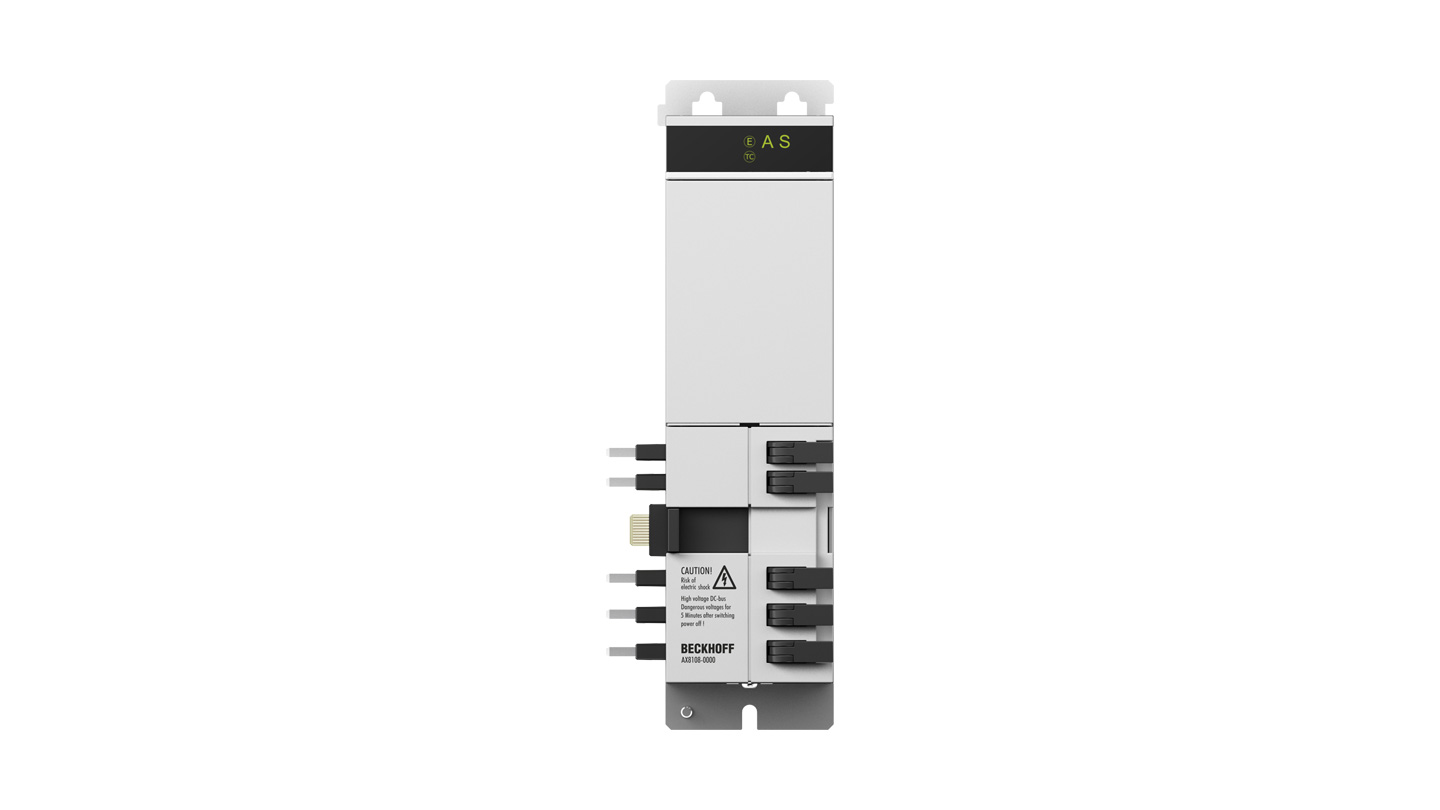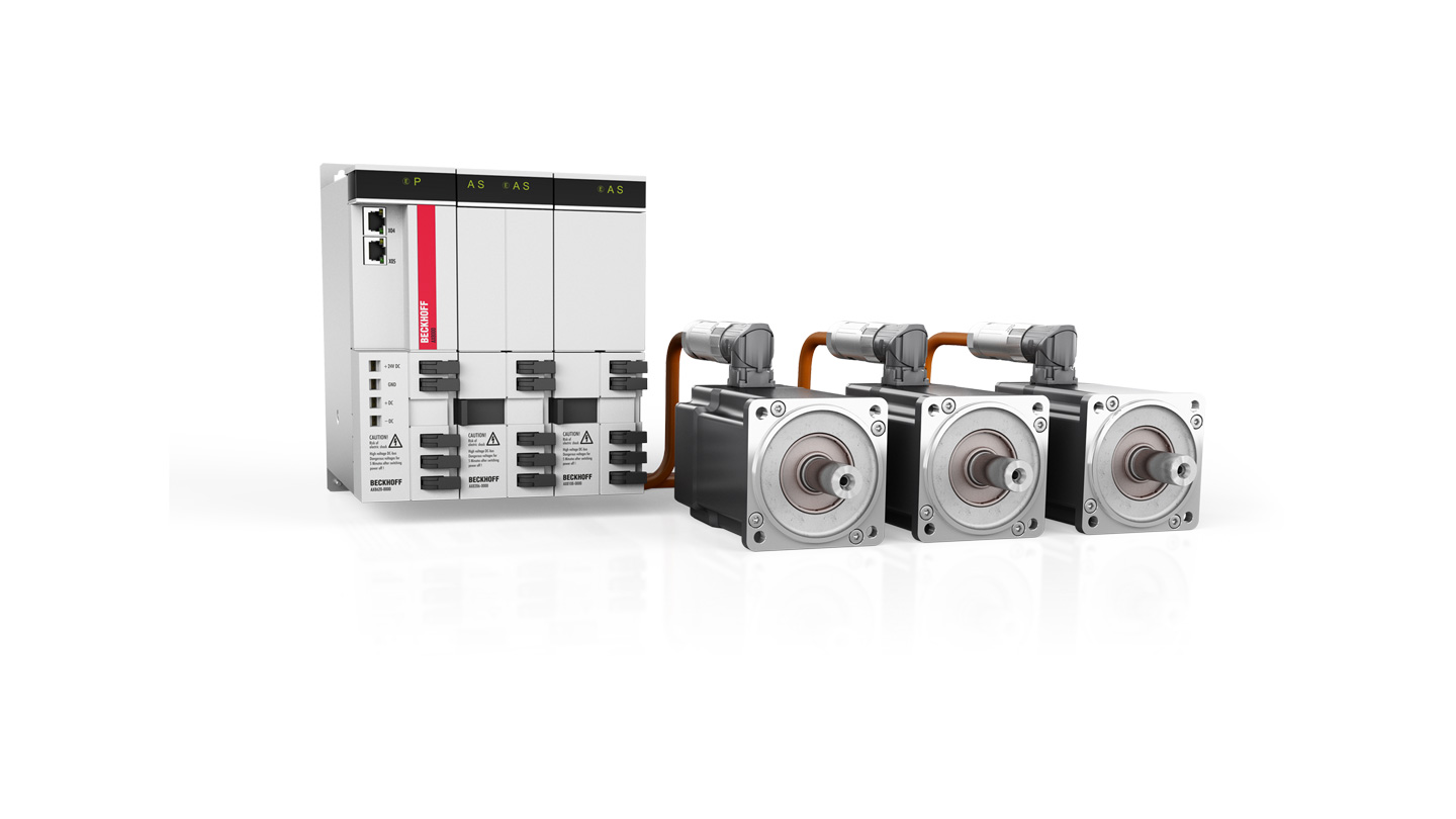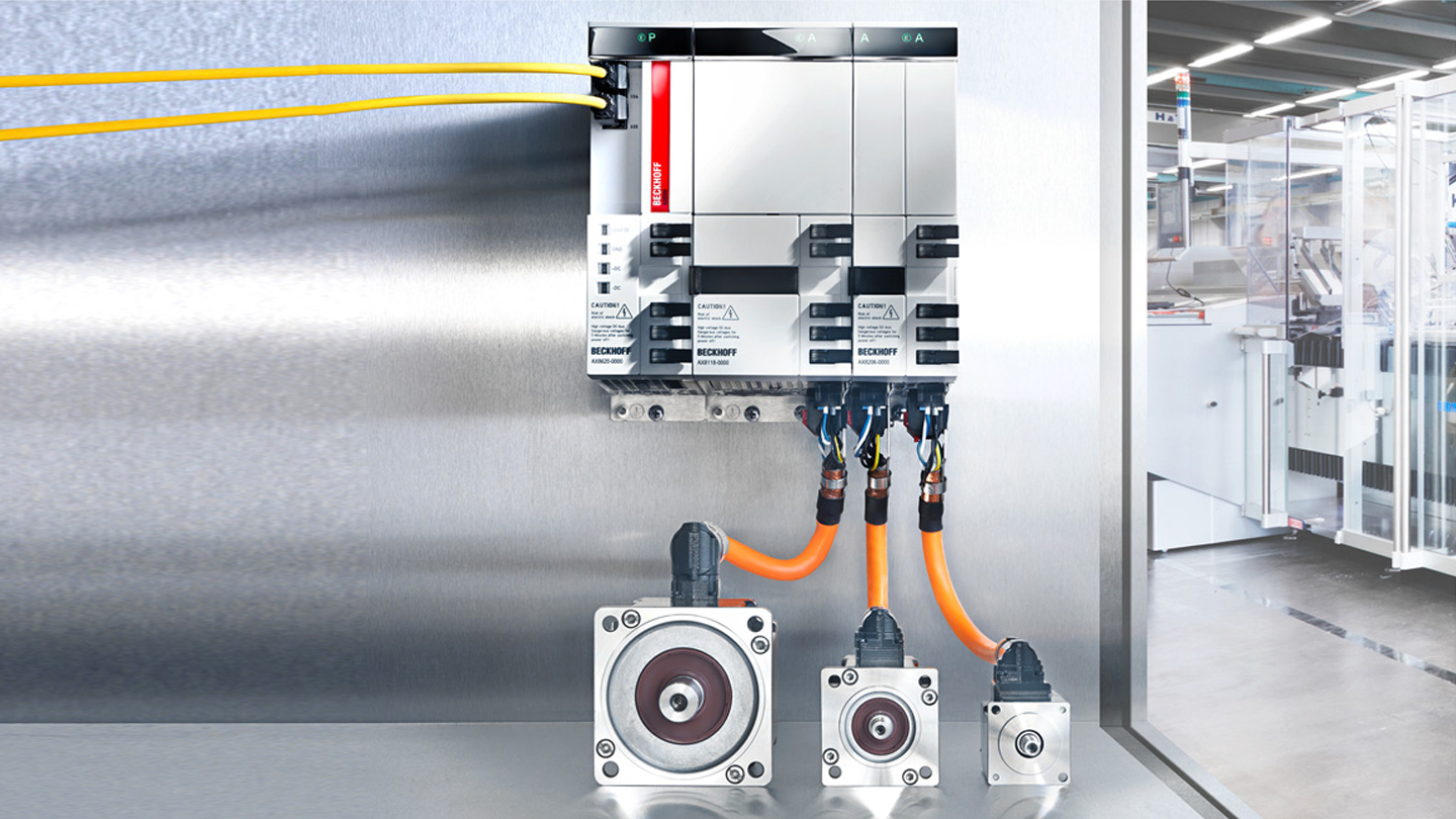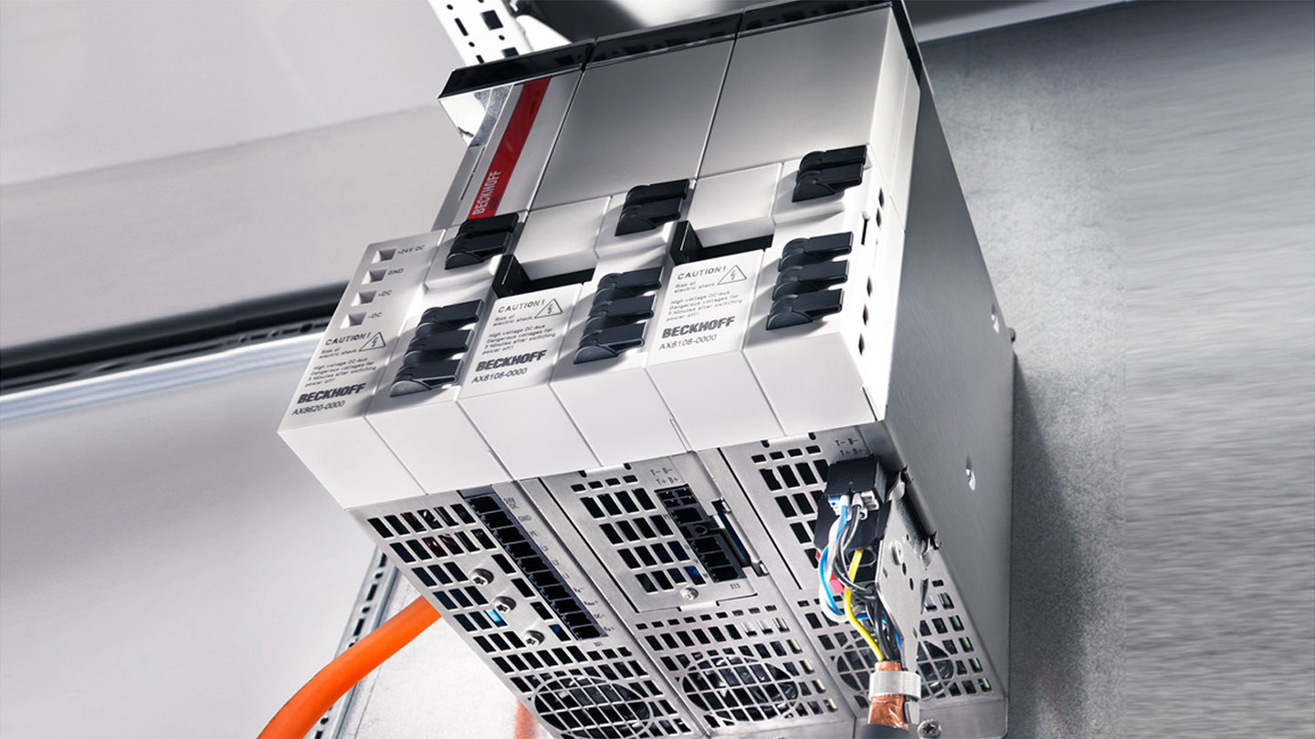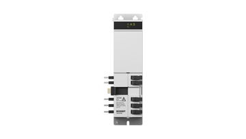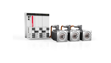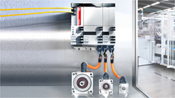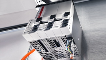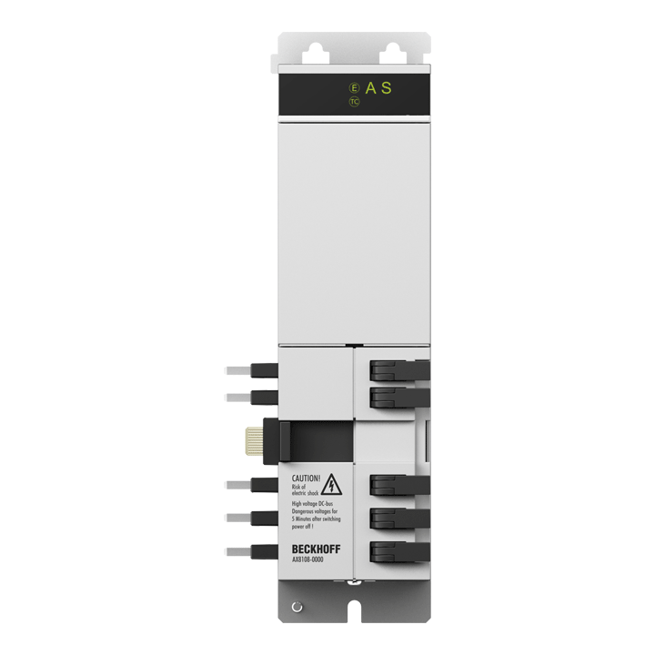
An axis module contains the DC link and the inverter for supplying the motor. Depending on the required number of axes, the axis modules are attached to the power supply module to form the multi-axis servo system. Axis modules with different ratings can be combined in order to enable an optimized design of the individual axes.
Supporting a wide supply voltage range from 100 to 480 V AC, the axis modules can be operated without limitation with any of the power supply modules. This flexibility simplifies the implementation of machine configurations for any type of mains supply. The electrical connection is established without tools via the already integrated AX-Bridge: it automatically connects DC link, 24 V DC control voltage and communication via EtherCAT between the linked modules. The DC link connection enables the exchange of energy during acceleration and braking procedures, where the regenerative brake energy is primarily stored in the common DC link. If the energy exceeds the DC link capacitance, the brake resistor of the AX881x capacitor modul is used to suppress the DC link voltage. The AX8000 multi-axis servo drive system encompasses new functions of safe drive technology with TwinSAFE: the AX8108, AX8118 and AX8206 axis modules include a programmable TwinSAFE Logic corresponding to an EL6910 and enable the direct implementation of a safety application in the servo drive. The user has greater degrees of freedom in the implementation of safety applications in drive technology systems, and the flexibility in programming facilitates individual design of safe drive technology to suit the specific system. The safety functions STO and SS1 can be implemented with the TwinSAFE axis modules with the ordering option -01x0 (STO/SS1). These functions can be initiated both via hard wiring and via FSoE. For TwinSAFE axis modules with the ordering option -02x0 (Safe Motion), various internal and external drive signals are available for implementing an application-specific safety function. As usual, these can be interconnected with the typical EL6910 pre-certified function blocks to form complex, safe drive functions such as SLS, SLP, etc. Depending on the application, the safety-oriented information can be pre-processed directly in the drive so that the central TwinSAFE Logic need only process the information that is aggregated there.
The multi-feedback interface supports the digital encoder systems EnDat® 2.2/22 and BiSS® C (ordering option -0x10) and the analog encoder systems DIFF RS422, TTL and SinCos 1 VPP (ordering option -0x20). Two further D-sub 15-pin connectors can be found behind the front cover. Therefore, one or two EnDat® or BiSS® encoders can be connected to a single-axis module. With a dual-axis module, an encoder interface is assigned to each axis.
These encoder systems can be used as primary or secondary feedback interfaces. Primary feedback means that these encoders are used as commutation encoders. This is the case with third-party motors or if a Beckhoff linear motor is operated with this feedback. Example of secondary feedback: An AM8000 servomotor with OCT drives a spindle axis that is additionally equipped with a linear encoder to increase the accuracy.
Safety projects can be created quickly and easily with the TwinCAT 3 Safety Editor. The TwinSAFE Loader/User is also available as additional support.
Product status:
product announcement | estimated market release April 2025
Product information
| Technical data | AX8108-0220-0000 |
|---|---|
| Function | axis module with TwinSAFE Logic and multi-feedback interface |
| Channels | 1 |
| DC link voltage | max. 848 V DC |
| Rated output current (channel) | 8 A |
| Peak output current (channel) | 20 A |
| Feedback | OCT, EnDat® 3, BiSS® C, EnDat® 2.2/22, DIFF RS422, TTL, SinCos 1 VPP |
| System bus | EtherCAT |
| Drive profile | CiA402 according to IEC 61800-7-201 (CoE) |
| Realization STO | by local TwinSAFE Logic, via FSoE or hard-wired via safe inputs |
| Safe stop functions | Safe Torque Off (STO), Safe Operating Stop (SOS), Safe Stop 1 (SS1), Safe Stop 2 (SS2) |
| Safe acceleration functions | Safe Maximum Acceleration (SMA), Safe Acceleration Range (SAR) |
| Safe braking functions | Safe Brake Control (SBC), Safe Brake Test (SBT) |
| Safe direction functions | Safe Direction positive (SDIp), Safe Direction negative (SDIn) |
| Safe speed functions | Safely Limited Speed (SLS), Safe Speed Range (SSR), Safe Speed Monitor (SSM), Safe Maximum Speed (SMS) |
| Safe position functions | Safely Limited Position (SLP), Safe CAM (SCA), Safely Limited Increment (SLI) |
| Safety standard | EN ISO 13849-1:2015 (Cat 4, PL e), EN 61508:2010 (SIL 3) and EN 62061:2005 + A1:2013/A2:2015 (SIL CL3) |
| Ambient temperature (operation) | 0…40°C, up to 55°C with power reduction (see documentation) |
| Approvals/markings | CE, cULus, EAC |
| Housing data | AX8108-xxxx |
|---|---|
| Protection rating | IP20 |
| Width | 60 mm |
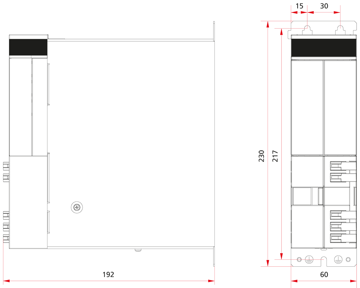
| Dimensions | AX8108-0220-0000 |
|---|---|
| Height without connectors | 230 mm |
| Depth without connectors | 192 mm |
| Width | 60 mm |
Loading content ...
Loading content ...
Loading content ...
Loading content ...
Loading content ...
© Beckhoff Automation 2025 - Terms of Use
