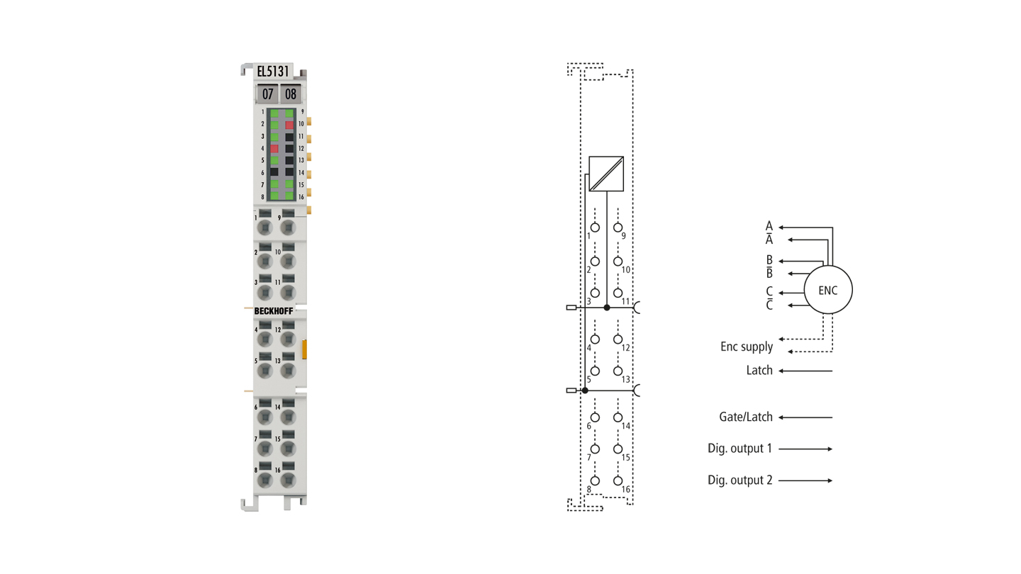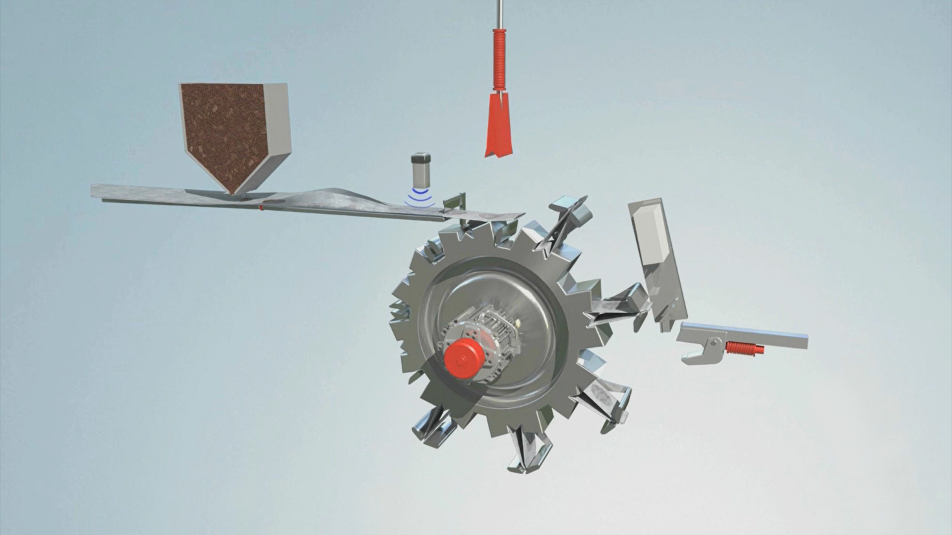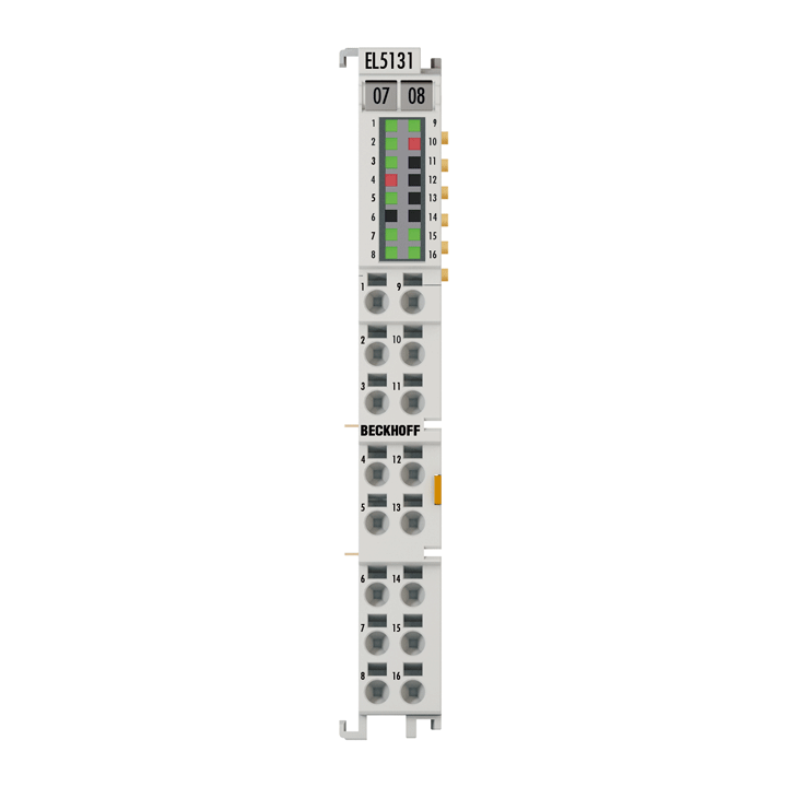
The EL5131 EtherCAT Terminal is an interface for the direct connection of incremental encoders with differential signals (RS422) or single-ended signals (TTL and open collector). Two parameterizable 24 V DC push-pull, tristate outputs are available, which are set after reaching a specified count, frequency or speed value. This allows the realization of a digital cam controller, which uses position or time cams and ensures a precise response time independent of the fieldbus cycle.
Two additional 24 V digital inputs are available for storing, blocking and setting the counter status. It is also possible to set the counter to a predefined value or to lock the counter directly through the process data. The error message output of an encoder can be connected and evaluated via the status input. The 5 V, 12 V or 24 V supply of the encoder can be provided directly via the terminal connection points.
Special features:
- save, lock, set counter
- parameterizable 2 x 24 V push-pull, tristate outputs
- digital cam controller with position cams or time cams
- integrated frequency measurement
- optionally usable as 5 V up/down counter
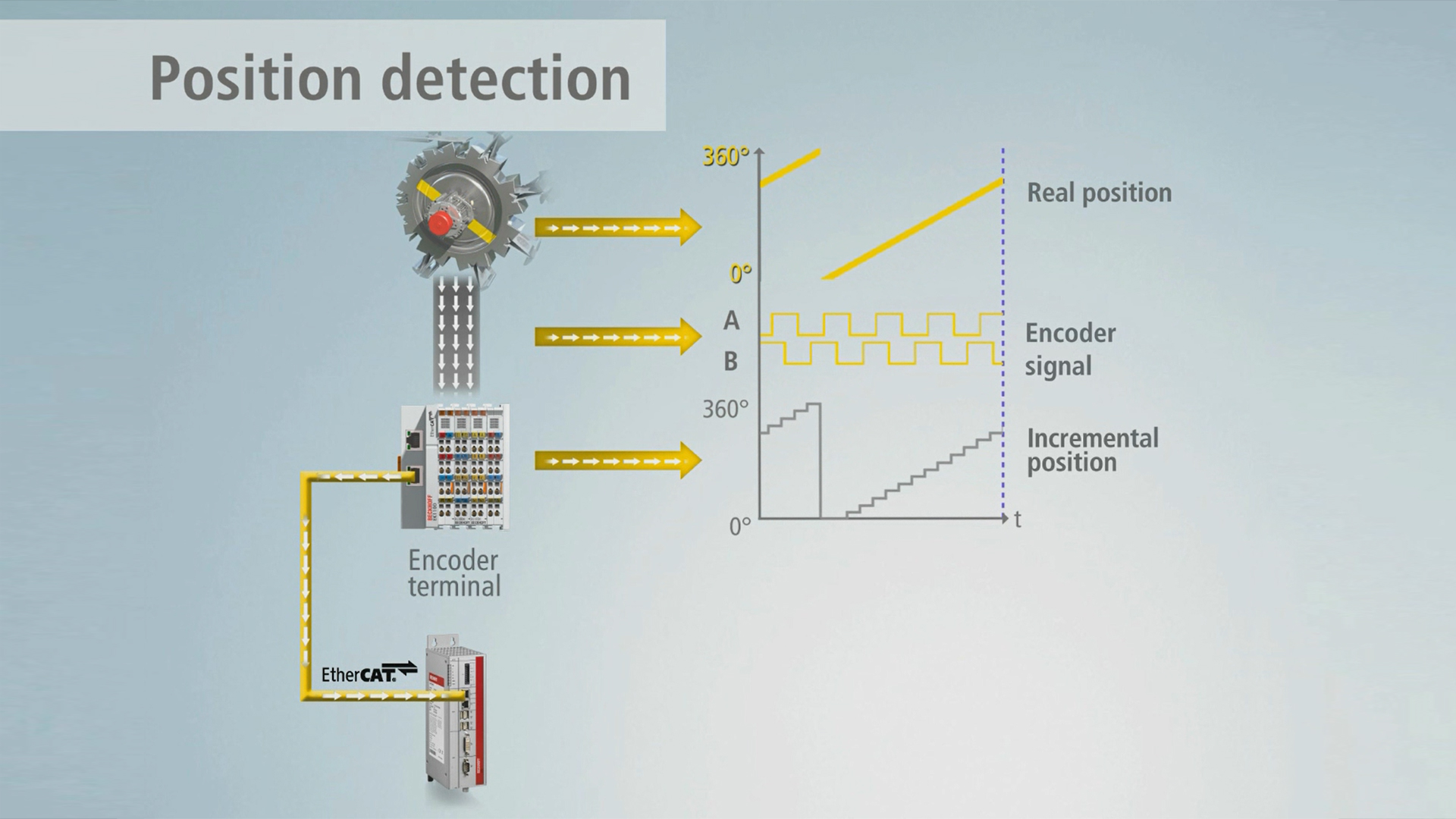
- microincrements
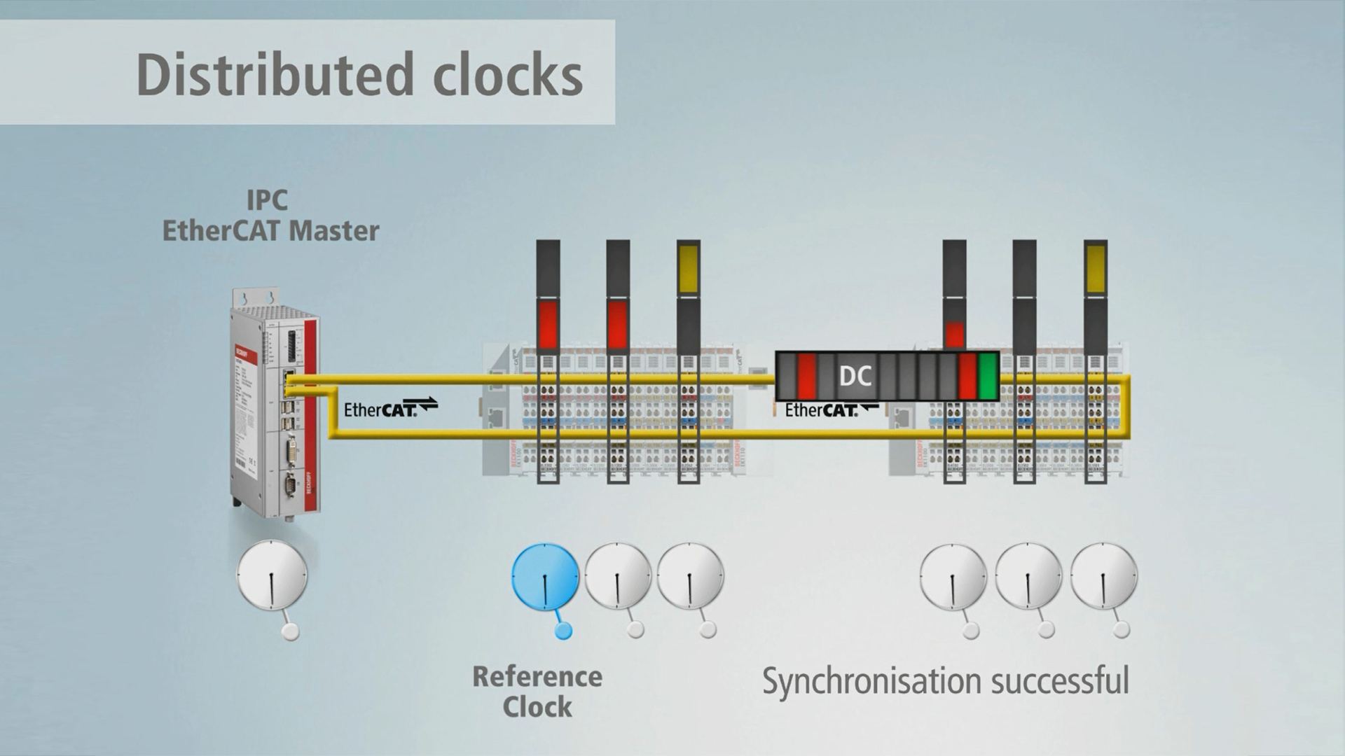
- synchronous reading of the position value via distributed clocks
- timestamp on the last registered incremental edge, latch values and the output switching limits
In addition, the EL5131 enables the measurement of a frequency or velocity with a resolution of 10 ns. A duty cycle measurement of the input signal is implemented.
With the optional interpolating microincrement functionality, the EL5131 can provide even more accurate axis positions for dynamic axes. It also supports synchronous reading of the encoder value together with other input data in the EtherCAT system via the high-precision EtherCAT distributed clocks (DC). Additionally, timestamps are available for the last registered incremental edge, the edge at the latch input, the zero pulse track C and the output switching limits. The use of encoder profiles enables simple and fast linking of the process data for motion control applications.
Product status:
regular delivery
Product information
| Technical data | EL5131 |
|---|---|
| Technology | incremental encoder interface, differential (RS422), single-ended (TTL, open collector), counter, pulse generator |
| Number of channels | 1 |
| Encoder connection | 1 x A, B, C
differential inputs (RS422): A, A̅ (inv), B, B̅ (inv), C, C̅ (inv) single-ended connection (TTL, open collector): A, B, C counter, pulse generator: A, B |
| Additional inputs | latch, gate/latch (24 V DC, TON > 1 µs),
status input (max. 5 V DC, negative switching, TON > 10 µs) |
| Additional outputs | 2 x push pull, ohmic switchable (tristate) |
| Encoder operating voltage | 5 V DC (default), 12 V DC, 24 V DC switchable, 0.3 A (generated from the 24 V DC power contacts) |
| Load type | outputs ohmic, inductive, lamp load |
| Nominal output voltage | 24 V DC (-15%/+20%) |
| Output current | push mode: max. 0.5 A per channel, pull mode: 0.15 A per channel |
| Switching times | outputs: typ. TON: 3 µs (push mode), typ. TOFF: 4 µs (pull mode), typ. 7 µs (tristate mode) |
| Short-circuit current | typ. < 1 A (push mode), typ. < 0,2 A (pull mode) |
| Counter | 32 bit (default), 16/32 bit switchable |
| Limit frequency | RS422: 20 million increments/s with 4-fold evaluation, corresponding to 5 MHz, TTL: 4 million increments/s with 4-fold evaluation, corresponding to 1 MHz, open collector: 400 kilo increments/s with 4-fold evaluation, corresponding to 100 kHz |
| Quadrature decoder | 4-fold evaluation (default), 2-fold, 1-fold evaluation switchable |
| Distributed clocks | yes |
| Resolution | 1/256 bit microincrements |
| Current consumption power contacts | typ. 20 mA + load |
| Current consumption E-bus | typ. 240 mA |
| Wiring fail indication | yes, for RS422 encoder |
| Electrical isolation | 500 V (E-bus/field potential) |
| Special features | open-circuit recognition, frequency, speed and duty cycle measurement, microincrements, timestamp on last incremental edge, zero pulse C, latch input, gate/latch 2 input and to the output switching limits |
| Weight | approx. 50 g |
| Operating temperature | 0…55°C |
| Storage temperature | -25…+85°C |
| Relative humidity | 95%, no condensation |
| Vibration/shock resistance | conforms to EN 60068-2-6/EN 60068-2-27 |
| EMC immunity/emission | conforms to EN 61000-6-2/EN 61000-6-4 |
| Protect. rating/installation pos. | IP20/variable |
| Approvals/markings | CE, UL |
| Housing data | EL-12-16pin |
|---|---|
| Design form | HD (High Density) housing with signal LEDs |
| Material | polycarbonate |
| Installation | on 35 mm DIN rail, conforming to EN 60715 with lock |
| Side by side mounting by means of | double slot and key connection |
| Marking | labeling of the BZxxxx series |
| Wiring | solid conductors (s): direct plug-in technique; fine-stranded conductors (st) and ferrule (f): spring actuation by screwdriver |
| Connection cross-section | s*: 0.08…1.5 mm², st*: 0.25…1.5 mm², f*: 0.14…0.75 mm² |
| Connection cross-section AWG | s*: AWG28…16, st*: AWG22…16, f*: AWG26…19 |
| Stripping length | 8…9 mm |
| Current load power contacts | Imax: 10 A |
| Dimensions (W x H x D) | 12 mm x 100 mm x 68 mm |
*s: solid wire; st: stranded wire; f: with ferrule
Loading content ...
Loading content ...
Loading content ...
Loading content ...
Loading content ...
© Beckhoff Automation 2025 - Terms of Use
