DetachFixClose

Headquarters Canada
Beckhoff Automation Ltd.

4 Schiedel Court, Unit 1-3
Cambridge ON N3C 0H1, Canada

+1 226-765-7700
www.beckhoff.com/en-ca/

EtherCAT – the Ethernet Fieldbus

Selecting the communication technology is important: it determines whether the control performance will reach the field and which devices can be used. EtherCAT, the Industrial Ethernet technology invented by Beckhoff, makes machines and systems faster, simpler and more cost-effective. EtherCAT is regarded as the "Ethernet fieldbus" because it combines the advantages of Ethernet with the simplicity of classic fieldbus systems and avoids the complexity of IT technologies. The EtherCAT Technology Group (ETG), founded in 2003, makes it accessible to everyone. With over 7,000 member companies from 72 countries (as of March 2023), the ETG is the world's largest fieldbus user organization.

EtherCAT is an international IEC standard that not only stands for openness, but also for stability: until today, the specifications have never been changed, but only extended compatibility. This means that current devices can be used in existing systems without any problems and without having to consider different versions. The extensions include Safety over EtherCAT for machine and personnel safety in the same network, and EtherCAT P for communication and supply voltage (2 x 24 V) on the same 4-wire cable. And also EtherCAT G/G10, which introduces higher transfer rates, while the existing EtherCAT equipment variety is integrated via the so called branch concept: even here there is no technology break.

Products
EtherCAT Terminals

EtherCAT Terminals

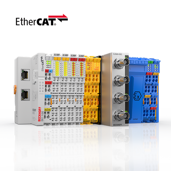
The EtherCAT Terminal system provides a comprehensive range of products for all signals in the world of automation.
EtherCAT Box

EtherCAT Box

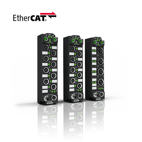
EtherCAT high-performance directly in the field: Beckhoff offers an I/O system in IP67 with the EtherCAT Box modules.
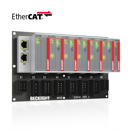
EtherCAT plug-in modules

EtherCAT plug-in modules

The EtherCAT plug-in modules reduce the wiring work and system installation time with standard machines.
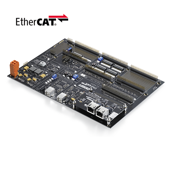
EtherCAT development products

EtherCAT development products

With the EtherCAT development products a simple and cost-effective integration of the technology into own products is possible.
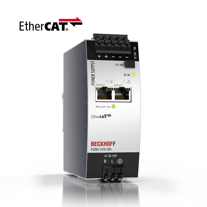
PS2000 with EtherCAT

PS2000 with EtherCAT

Single and 3-phase DIN rail power supply units in compact design, can be used for the most common applications.
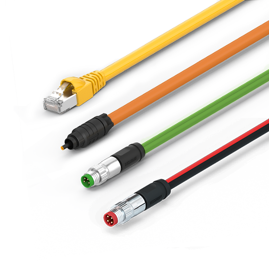
EtherCAT and fieldbus cables

EtherCAT and fieldbus cables

The EtherCAT and fieldbus cables ensure reliable data transmission and are optimized for industrial applications and harsh environmental conditions.

MX-System

MX-System

Our MX-System combines all technological innovations in automation technology in an IP67-capable modular system.

Engineer´s choice: the 6 key benefits of EtherCAT

EtherCAT is by and large the fastest Industrial Ethernet technology, but it also synchronizes with nanosecond accuracy. This is a huge benefit for all applications in which the target system is controlled or measured via the bus system. The rapid reaction times work to reduce the wait times during the transitions between process steps, which significantly improves application efficiency. Lastly, the EtherCAT system architecture typically reduces the load on the CPU by 25 - 30 % in comparison to other bus systems (given the same cycle time). When optimally applied, the performance of EtherCAT leads to improved accuracy, greater throughput and lowered costs.

In EtherCAT applications, the machine structure determines the network topology, not the other way around. In conventional Industrial Ethernet systems, there are limitations on how many switches and hubs can be cascaded, which thus limits the overall network topology. Since EtherCAT does not need hubs or switches, there are no such limitations. In short, EtherCAT is virtually limitless when it comes to network topology. Line, tree, star topologies and any combinations thereof are possible with a nearly unlimited number of nodes. Thanks to the Hot Connect functionality, nodes and network segments can be disconnected during operation and then reconnected – even somewhere else. Line topology is extended to a ring topology for the sake of cable redundancy. All the master device needs for this redundancy is a second Ethernet port, and the slave devices already support the cable redundancy. This makes switching out devices during machine operation possible.

Configuration, diagnostics and maintenance are all factors that contribute to system costs. The Ethernet fieldbus makes all of these tasks significantly easier: EtherCAT can be set to automatically assign addresses, which eliminates the need for manual configuration. A low bus load and peer-to-peer physics improve electromagnetic noise immunity. The network reliably detects potential disturbances down to their exact location, which drastically reduces the time needed for troubleshooting. During startup, the network compares the planned and actual layouts to detect any discrepancies. EtherCAT performance also helps during system configuration by eliminating the need for network tuning. Through the large bandwidth, there is capacity to transmit additional TCP/IP together with the control data. However, since EtherCAT itself is not based on TCP/IP, there is no need to administer MAC addresses or IP addresses or to have IT experts configure switches and routers.

Functional safety as an integrated part of the network architecture? Not a problem with Fail Safe over EtherCAT (FSoE). FSoE is proven in use through TÜV-certified devices that have been on the market since 2005. The protocol fulfills the requirements for SIL3 systems and is suitable for both centralized and decentralized control systems. Through the Black Channel approach and the particularly lean safety container, FSoE can be used in other bus systems. This integrated approach and the lean protocol help keep system costs down. Additionally, a non-safety critical controller can also receive and process safety data.

EtherCAT delivers the features of Industrial Ethernet at a price similar or even below that of a classic fieldbus system. The only hardware required by the master device is an Ethernet port – no expensive interface cards or co-processors are necessary. EtherCAT Slave Controllers are available from various manufacturers in different formats: as an ASIC, based on FPGA or as an option for standard microprocessor series. Since these inexpensive controllers shoulder all the time-critical tasks, EtherCAT itself does not place any performance requirements on the CPU of slave devices, which keeps device costs down. Since EtherCAT does not require switches or other active infrastructure components, the costs for these components and their installation, configuration and maintenance are also eliminated.

EtherCAT is the Industrial Ethernet technology with by far the largest variety of vendors and devices on the market. And since Beckhoff invented EtherCAT, vendors try their EtherCAT products with TwinCAT, the gold standard for EtherCAT controllers. With over 1,000 EtherCAT devices, Beckhoff has the largest EtherCAT product portfolio - which can, however, be supplemented with the offerings of 3,000 officially registered vendors if required. And what is not yet available can be developed comparatively easily: the EtherCAT Slave Controller chips make it possible.

The technology in detail

EtherCAT is an Industrial Ethernet system and utilizes standard frames and the physical layer as defined in the Ethernet standard IEEE 802.3. However, it also addresses the specific demands faced in the automation industry, where:

  • There are hard real-time requirements with deterministic response times.
  • The system is usually made up of many nodes, each only having a small amount of cyclic process data.
  • Fieldbus systems are not commissioned and maintained by IT administrators


The above requirements make using a standard Ethernet network at the field level practically impossible. If an individual Ethernet telegram is used for each node, the effective data rate sinks significantly for just a few bytes of cyclic process data: the shortest Ethernet telegram is 84 bytes long (including the Inter FrameGap), of which 46 bytes can be used for process data.

For example, if a drive sends 4 bytes of process data for the actual position and status information and receives 4 bytes of data for the target position and control information, the effective data rate for both telegrams sinks to 4/84 = 4.8 %. Additionally, the drive usually has a reaction time that triggers the transmission of the actual values after receiving the target values. At the end, not much of the 100 Mbit/s transfer rate remains. Protocol stacks, such as those used in the IT world for routing (IP) and connection (TCP), require additional overhead for each node and create further delays through the stack runtimes. Managing MAC and IP addresses, SNMP, IGMP snooping, routers and switches is not for everyone.

EtherCAT functional principle

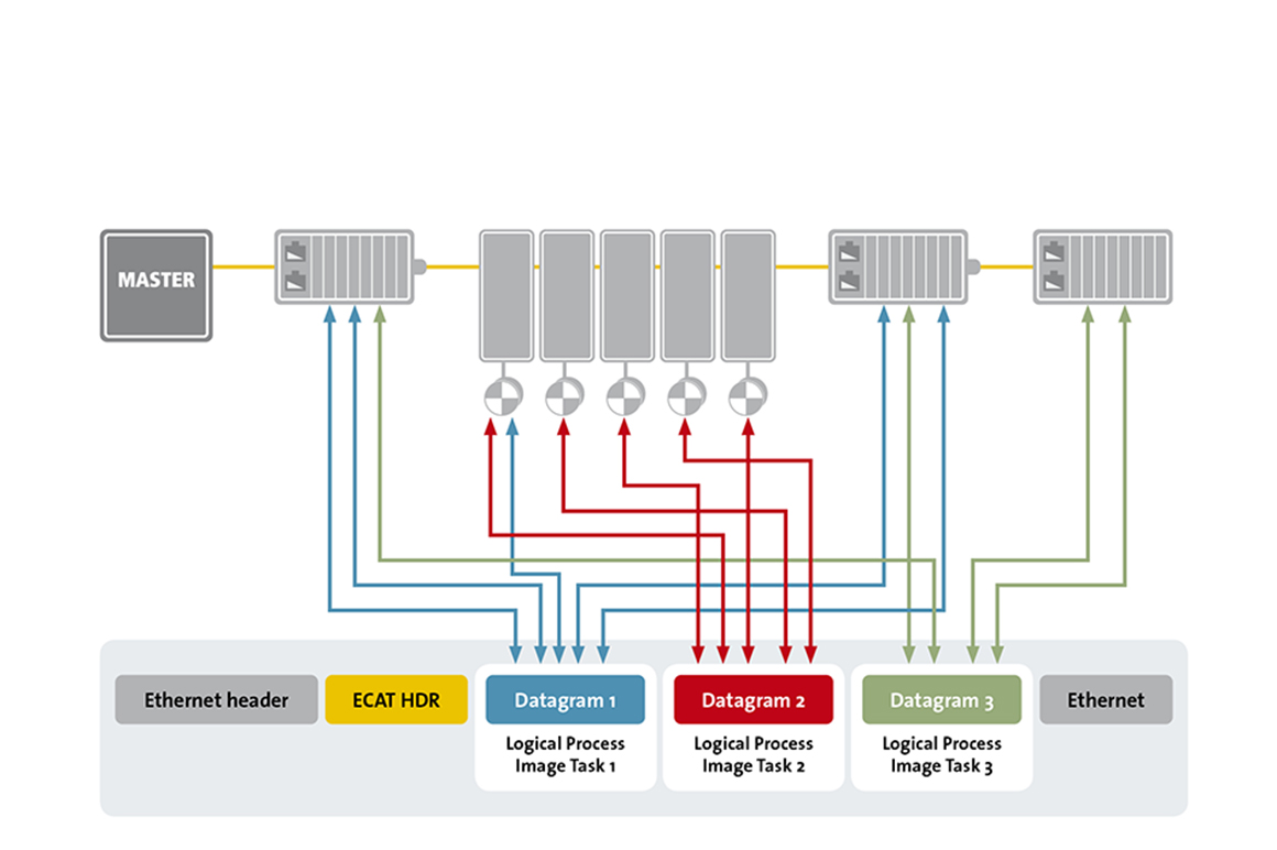
EtherCAT overcomes the typical shortcomings of Industrial Ethernet with its high-performing mode of operation, in which a single frame is usually sufficient to send and receive control data to and from all nodes. The EtherCAT master sends a telegram that passes through each node. Each EtherCAT slave device reads the data addressed to it “on the fly” and inserts its data in the frame as the frame is moving downstream. The frame is delayed only by hardware propagation delay times. The last node in a segment or branch detects an open port and sends the message back to the master using the full duplex feature.The telegram’s maximum effective data rate increases to more than 90 %, and due to the utilization of the full duplex feature, the theoretical effective data rate is even greater than 100 Mbit/s. The EtherCAT master is the only node within a segment allowed to actively send an EtherCAT frame; all other nodes merely forward frames downstream. This concept prevents unpredictable delays and guarantees real-time capabilities. The master uses a standard Ethernet Media Access Controller (MAC) without an additional communication processor. This allows a master to be implemented on any hardware platform with an available Ethernet port, regardless of which real-time operating system or application software is used. EtherCAT slave devices use a so-called EtherCAT Slave Controller (ESC) to process frames on the fly and entirely in hardware, making network performance predictable and independent of the individual slave device implementation.

EtherCAT embeds its payload in a standard Ethernet frame. Since the EtherCAT protocol is optimized for short cyclic process data, the use of bulky protocol stacks, such as TCP/IP or UDP/IP, can be eliminated. Ethernet IT communication between the nodes can optionally be tunneled through a mailbox channel without impacting real-time data transfer. The EtherCAT frame contains the frame header and one or more datagrams. The datagram header indicates what type of access the master device would like to execute:

  • read, write, or read-write
  • access to a specific slave device through direct addressing, or access to multiple slave devices through implicit addressing

Implicit addressing is used for the cyclical exchange of process data. Each datagram addresses a specific part of the process image in the EtherCAT segment, for which 4 GB of address space is available. During network startup, each slave device is assigned one or more addresses in this global address space. If multiple slave devices are assigned addresses in the same area, they can all be addressed with a single datagram.

Since the datagrams completely contain all the data access related information, the master device can vary the frame composition and thus decide when and which data to access. For example, the master device can use short cycle times to refresh data on the drives, while using a longer cycle time to sample the I/O; a fixed process data structure is not necessary.

In addition to logical addressing, the master device can also address a slave device via its position in the network. This method is used during network boot up to determine the network topology and compare it to the planned topology. After checking the network configuration, the master device can assign each node a configured node address and communicate with the node via this fixed address. This enables targeted access to devices, even when the network topology is changed during operation, for example with Hot Connect groups. In addition to cyclical data, further datagrams can be used for asynchronous or event driven communication.

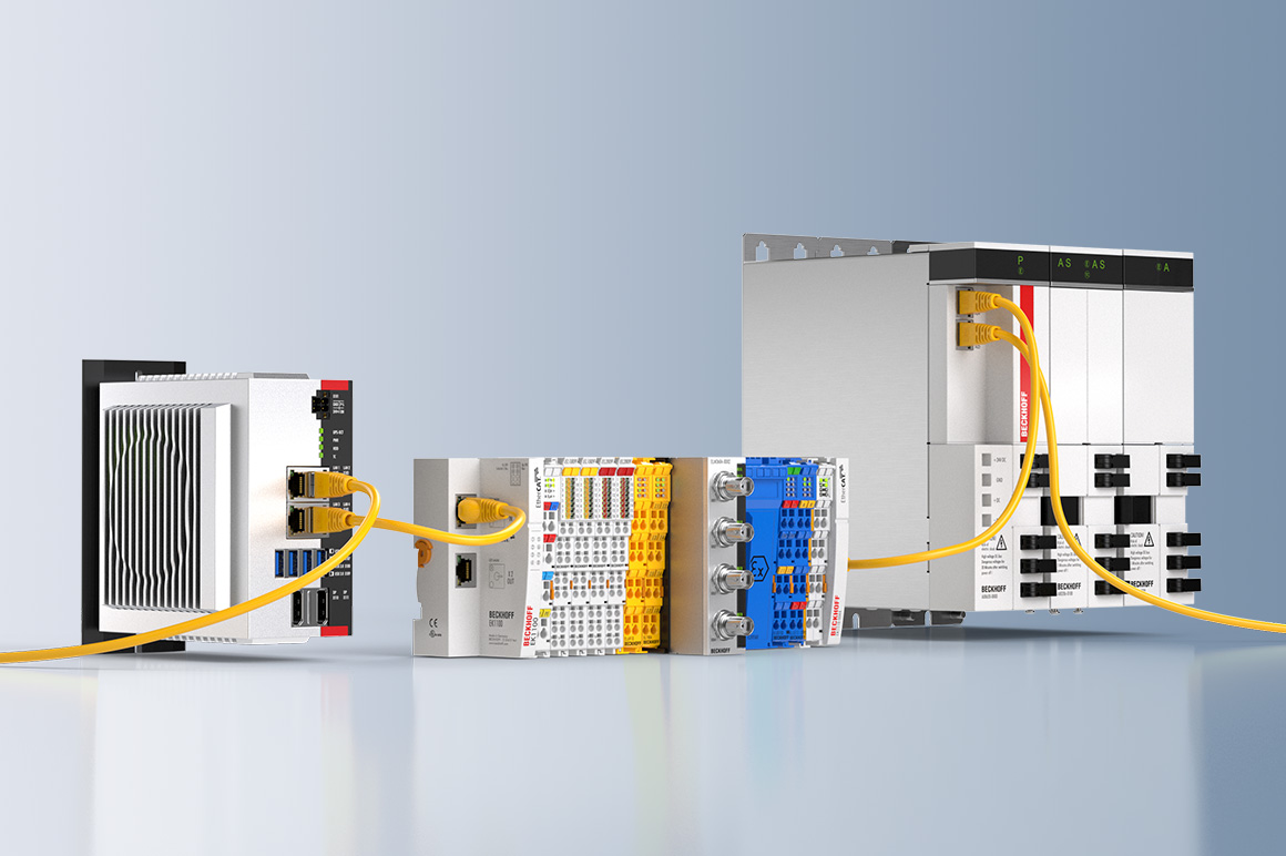
Line, tree, star or daisy-chain: EtherCAT supports almost all topologies. Pure bus or line topologies with many nodes are possible without limitations. When wiring the system, the combination of lines with branches or drop lines is particularly beneficial: the ports necessary to create branches are directly integrated in many I/O modules, so no additional switches or active infrastructure components are required. Naturally, the star topology, the Ethernet classic, can also be utilized.

Modular, complex machines switch network segments or individual nodes during operation (Hot Connect). EtherCAT slave controllers already include the basis for this feature. If a neighboring station is removed, the port is automatically closed so the rest of the network continues to operate without interference. Very short detection times < 15 μs guarantee a smooth changeover.

This incredible flexibility results from cable options: Inexpensive Industrial Ethernet cables can be used between two nodes up to 100 m apart in 100BASE-TX mode. Fiber optics (such as 100BASE-FX) can be used for distances greater than 100 m. The complete range of Ethernet wiring is also available for EtherCAT.

The ample bandwidth of EtherCAT makes it possible to embed conventional fieldbus networks as an underlying system via an EtherCAT gateway, which is particularly helpful when migrating from a conventional fieldbus to EtherCAT. The changeover to EtherCAT is gradual, making it possible to continue using automation components that do not yet support an EtherCAT interface.

EtherCAT supports up to 65,535 devices per segment, so network expansion is virtually unlimited. Because of the practically unlimited number of nodes, modular devices such as “sliced” I/O stations are designed in such a way that each module is an EtherCAT node of its own. Hence, the local extension bus is eliminated; the high performance of EtherCAT reaches each module directly and without any delays, since there is now no gateway in the bus coupler or head station.

In applications with spatially distributed processes requiring simultaneous actions, exact synchronization is particularly important. For example, this is the case for applications in which multiple servo axes execute coordinated movements. As explained in more detail below, an exact time base is also important for controlling a single axis.

In contrast to completely synchronous communication, whose quality suffers immediately from communication errors, distributed synchronized clocks have a high degree of tolerance for jitter in the communication system. Therefore, the EtherCAT solution for synchronizing nodes is based on such distributed clocks (DC). The calibration of the clocks in the nodes is completely hardware-based. The time from the first DC slave device is cyclically distributed to all other devices in the system. With this mechanism, the slave device clocks can be precisely adjusted to this reference clock. The resulting jitter in the system is significantly less than 1 μs, usually in the double-digit nanosecond range.

Since the time sent from the reference clock arrives at the slave devices slightly delayed, this propagation delay must be measured and compensated for each slave device in order to ensure synchronicity and simultaneousness. This delay is measured during network startup or, if desired, even continuously during operation, ensuring that the clocks are simultaneous to within much less than 1 μs of each other.

If all nodes have the same time information, they can set their output signals simultaneously and affix their input signals with a highly precise timestamp. In motion control applications, cycle accuracy is also important in addition to synchronicity and simultaneousness. In such applications, velocity is typically derived from the measured position, so it is critical that the position measurements are taken precisely equidistantly (i.e. in exact cycles). Additionally, the use of distributed clocks also unburdens the master device; since actions such as position measurement are triggered by the local clock instead of when the frame is received, the master device doesn’t have such strict requirements for sending frames. This allows the master stack to be implemented in software on standard Ethernet hardware. Even jitter in the range of several microseconds does not diminish the accuracy of the Distributed Clocks! Since the accuracy of the clock does not depend on when it’s set, the frame’s absolute transmission time becomes irrelevant. The EtherCAT master needs only to ensure that the EtherCAT telegram is sent early enough, before the DC signal in the slave devices triggers the output.

Experience with conventional fieldbus systems has shown that diagnostic characteristics play a major role in determining a machine’s availability and commissioning time. In addition to error detection, error localization is important during troubleshooting. EtherCAT features the possibility to scan and compare the actual network topology with the planned topology during boot up. EtherCAT also has many additional diagnostic capabilities inherent to its system.

The EtherCAT Slave Controller in each node checks the moving frame for errors with a checksum. Information is provided to the slave application only if the frame has been received correctly. If there is a bit error, the error counter is incremented and the subsequent nodes are informed that the frame contains an error. The master device detects that the frame is faulty and discards its information. The master device is able to detect where the fault originally occurred in the system by analyzing the nodes’ error counters. This is an enormous advantage in comparison to conventional fieldbus systems, in which an error is propagated along the entire party line, making it impossible to localize the source of the error. EtherCAT can detect and localize occasional disturbances before the issue impacts the machine’s operation. Even a loose connector can be found quickly in EtherCAT thanks to the Link-Lost-Counter.

Thanks to the unique principle of band width utilization of EtherCAT, which is orders of magnitude better than industrial Ethernet technologies that use single frames, the likelihood of disturbances induced by bit errors within an EtherCAT frame is substantially lower – if the same cycle time is used. And, if in typical EtherCAT fashion much shorter cycle times are used, the time required for error recovery is significantly reduced. Thus, it is much simpler to master such issues within the application.

Since EtherCAT utilizes standard Ethernet frames, Ethernet network traffic can be recorded with the help of free Ethernet software tools. For example, the well-known Wireshark software comes with a protocol interpreter for EtherCAT, so that protocol-specific information, such as the Working Counter, commandos, etc. are shown in plain text. The master is then able to cyclically confirm if all nodes are working with consistent data. If the Working Counter has a different value than it should, the master does not forward this Datagram’s data to the control application. The master device is then able to automatically detect the reason for the unexpected behavior with help from status and error information from the nodes as well as the Link Status.

For machines or equipment with very high availability requirements, a cable break or a node malfunctioning should not mean that a network segment is no longer accessible, or that the entire network fails. EtherCAT enables cable redundancy with simple measures. By connecting a cable from the last node to an additional Ethernet port in the master device, a line topology is extended into a ring topology. A redundancy case, such as a cable break or a node malfunction, is detected by a software add-on in the master stack. That is all there is to it. The nodes themselves do not need to be modified, and do not even “know” that they are being operated in a redundant network.

Link detection in the slave devices automatically detects and resolves redundancy cases with a recovery time less than 15 μs, so at maximum, a single communication cycle is disrupted. This means that even motion applications with very short cycle times can continue working smoothly when a cable breaks.

With EtherCAT, it is also possible to realize master device redundancy with Hot Standby. Vulnerable network components, such as those connected with a drag chain, can be wired with a drop line, so that even when a cable breaks, the rest of the machine keeps running.

The evolution of EtherCAT

XFC

XFC

Based on an optimized control and communication architecture, XFC realizes response times of < 100 µs.

EtherCAT P

EtherCAT P

The one cable solution – One step closer to automation without control cabinets.
EtherCAT G

EtherCAT G

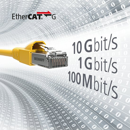
The continuation of the successful EtherCAT technology moves the available data rates up to 1 Gbit/s and 10 Gbit/s.

EtherCAT Technology Group – ETG

The EtherCAT Technology Group (ETG) keeps EtherCAT technology open for all potential users. It brings EtherCAT device manufacturers, technology providers, and users together to further the technology. They are focused on one common goal: keeping EtherCAT stable and interoperable. The ETG holds multiple Plug Fests in Europe, Asia, and America each year. The Plug Fests bring EtherCAT device developers together to test and ensure device interoperability. Using the official EtherCAT Conformance Test Tool, each manufacturer conformance tests its EtherCAT devices prior to their release. The ETG awards the manufacturer a Conformance Certificate following a successful test in an accredited test lab.

The ETG has the largest number of members out of any fieldbus organization in the world. The list of members can be found on its homepage. However, the decisive factor is not how many members there are, but how active the members are in the ETG. Both the number and variety of EtherCAT devices is unparalleled, and the adoption rate of EtherCAT across Europe, Asia, and America is outstanding.
Milestones

  • 2003 Introduction of EtherCAT technology at Hannover Messe
  • 2003 EtherCAT Technology Group founded at SPS IPC Drives
  • 2005 Safety over EtherCAT
  • 2007 EtherCAT is IEC standard.
  • 2016 EtherCAT P: ultra-fast communication and power via one cable
  • 2019 EtherCAT G: the next performance level with 1 Gbit/s